Actual signals and parameters 209
2604 IR COMP
FREQ
Defines the frequency at which the IR compensation is 0 V.
See the figure for parameter 2603 IR COMP VOLT
Note: If parameter 2605 U/F RATIO is set to USER
DEFINED, this parameter is not active. The IR
compensation frequency is set by parameter 2610 USER
DEFINED U1.
80%
0…100% Value in percent of the motor frequency 1 = 1%
2605 U/F RATIO Selects the voltage to frequency (U/f) ratio below the field
weakening point.
SQUARE
D
LINEAR Linear ratio for constant torque applications. 1
SQUARED Squared ratio for centrifugal pump and fan applications.
With squared U/f ratio the noise level is lower for most
operating frequencies.
2
USER
DEFINED
Custom ratio defined by parameters 2610…2618. See
section Custom U/f ratio on page 133.
3
2606 SWITCHING
FREQ
Defines the switching frequency of the drive. Higher
switching frequency results in lower acoustic noise. See
also parameter 2607 SWITCH FREQ CTRL and section
Switching frequency derating, I2N and ILD (= all currents)
on page 339.
In multimotor systems, do not change the switching
frequency from the default value.
4kHz
4 kHz 1 = 1 kHz
8 kHz
12 kHz
16 kHz
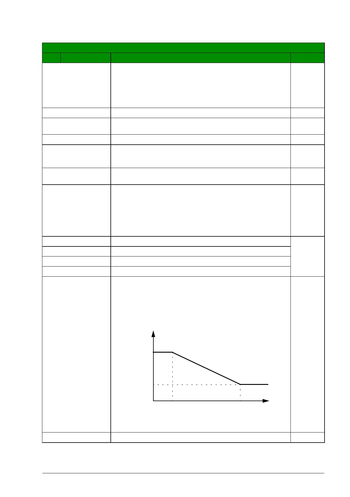
2607 SWITCH FREQ
CTRL
Activates the switching frequency control. When active, the
selection of parameter 2606 SWITCHING FREQ is limited
when the drive internal temperature increases. See the
figure below. This function allows the highest possible
switching frequency at a specific operation point.
Higher switching frequency results in lower acoustic noise,
but higher internal losses.
ON
ON Active 1
All parameters
No. Name/Value Description Def/FbEq
* Temperature depends on the drive output frequency.
16 kHz
4kHz
Drive
temperature
f
sw
limit
80…100 °C * 100…120 °C *
T

 Loading...


