Optional I/O extension modules 157
Electrical installation
Warnings
WARNING! Obey the instructions in chapter Safety instructions on page 13. If you
ignore them, injury or death, or damage to the equipment can occur. If you are not
a qualified electrician, do not do electrical work.
Make sure that the drive is disconnected from the input power during installation. If
the drive is already connected to the input power, wait for 5 minutes after
disconnecting the input power.
Necessary tools and instructions
• Screwdriver and a set of suitable bits
• Cabling tools
Terminal designations
For more detailed information on the connectors, see section Technical data on page 160.
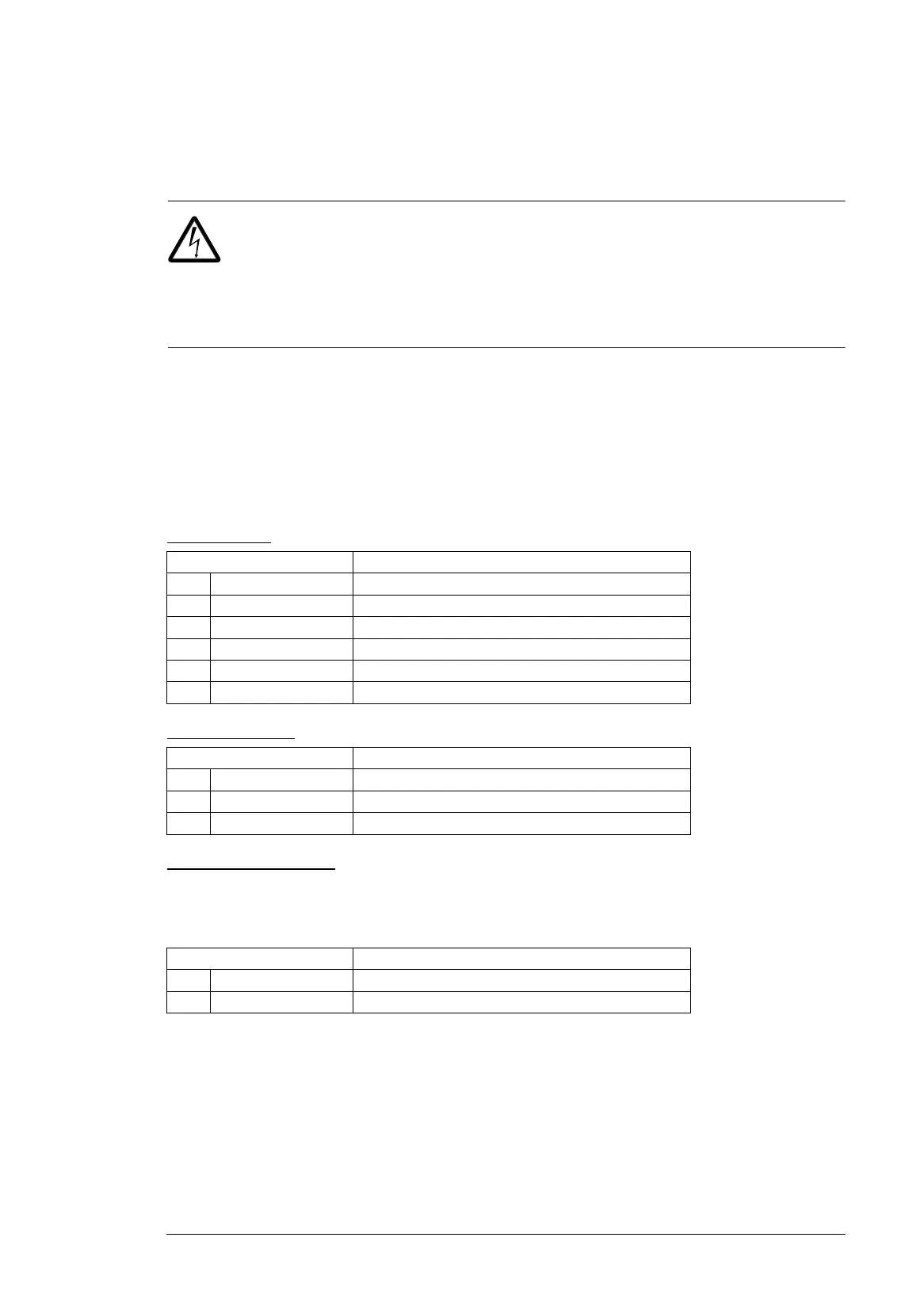
Relay outputs
Transistor output
External power supply
The external power supply is needed only if you want to connect an external back-up
power supply for the drive control unit.The control unit has corresponding terminals 40 and
41 for external power supply. connection
General cabling instructions
Obey the instructions given in chapter Guidelines for planning the electrical installation on
page 49.
Wiring
Connect the external control cables to the applicable module terminals. Ground the outer
shield of the cables 360 degrees under a grounding clamp next to the control unit.
Marking Description
50 RO4C Common, C
51 RO4A Normally closed, NC
52 RO4B Normally open, NO
53 RO5C Common, C
54 RO5A Normally closed, NC
55 RO5B Normally open, NO
Marking Description
42 DO1 SRC Source input
43 DO1 OUT Digital or frequency output
44 DO1 SGND Ground (earth) potential
Marking Description
40 24V AC/DC + in External 24 V (AC/DC) input
41 24V AC/DC - in External 24 V (AC/DC) input

 Loading...


