Control unit 83
Switches
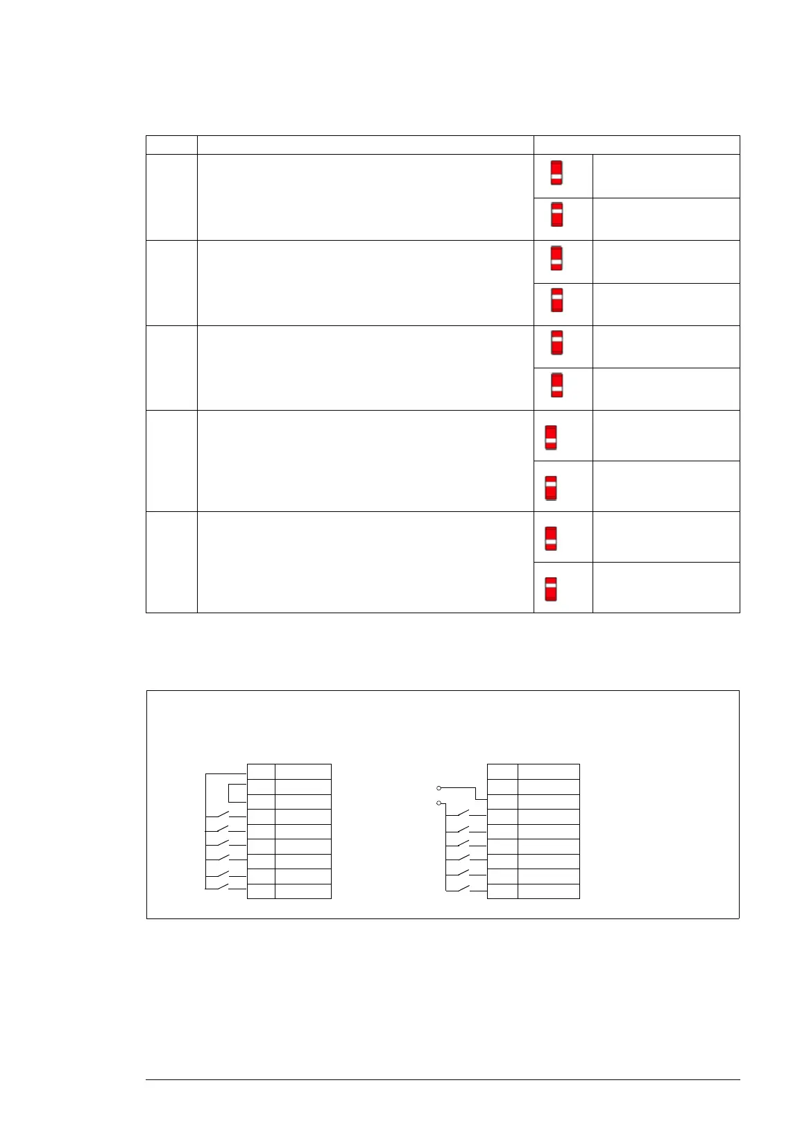
PNP configuration for digital inputs (DIGITAL IN)
Internal and external +24 V power supply connections for PNP configuration are shown in
the figure below.
Switch Description Position
AI1 Determines whether analog input AI1 is used as a voltage or
current input.
Voltage (U) (default)
Current (I)
AI2 Determines whether analog input AI2 is used as a voltage or
current input.
Voltage (U)
Current (I) (default)
AO1 Determines whether analog output AO1 is used as a current
or voltage output.
Current (I) (default)
Voltage (U)
TERM Drive-to-drive link termination. Must be set to the terminated
(ON) position when the drive (or another device) is the first or
last unit on the link.
Bus not terminated
(default)
Bus terminated
BIAS Switches on the biasing voltages to the bus. One (and only
one) device, preferably at the end of the bus must have the
bias on.
Bias off (default)
Bias on
PNP connection (source)
10 +24V
11 DGND
12 DCOM
13 DI1
14 DI2
15 DI3
16 DI4
17 DI5
18 DI6
PNP connection (source)
10 +24V
11 DGND
12 DCOM
13 DI1
14 DI2
15 DI3
16 DI4
17 DI5
18 DI6
+24 V DC
0VDC
Internal +24 V power supply External +24 V power supply

 Loading...


