68 Electrical installation
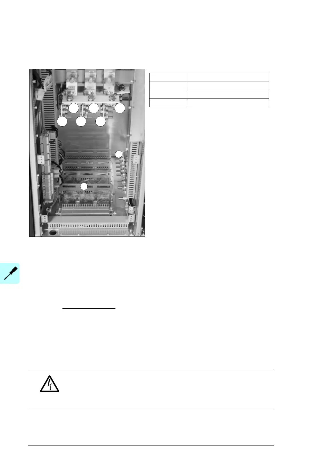
Layout of the input and motor cable connection terminals (frames
R10 and R11)
Connection procedure (IEC)
1. Do the steps in section Precautions before electrical work on page 16 before you start
the work.
2. Open the cabinet door.
3. Open the swing-out frame.
4. To remove the mounting plate(s) above the cabinet “door” fan, undo the mounting
screws. With option +G300:
Unplug the connectors at the back of the mounting plate.
5. To remove the fan mounting plate, loosen the mounting screws and lift the plate up.
Unplug the fan supply cables.
6. Remove the shrouds on the power cable terminals.
7. Peel off 3 to 5 cm of the outer insulation of the cables above the lead-through plate for
the 360° high-frequency grounding.
8. Prepare the ends of the cables.
WARNING! Apply grease to stripped aluminum conductors before attaching
them to non-coated aluminum cable lugs. Obey the grease manufacturer’s
instructions. Aluminum-aluminum contact can cause oxidation in the contact
surfaces.
9. If fire insulation is used, make an opening in the mineral wool sheet according to the
diameter of the cable.
W2V2U2
L1 L2 L3
1
1 Strain relief
L1, L2, L3 Input power cable terminals
U2, V2, W2 Motor cable terminals
2 PE terminal
2

 Loading...


