Electrical installation 71
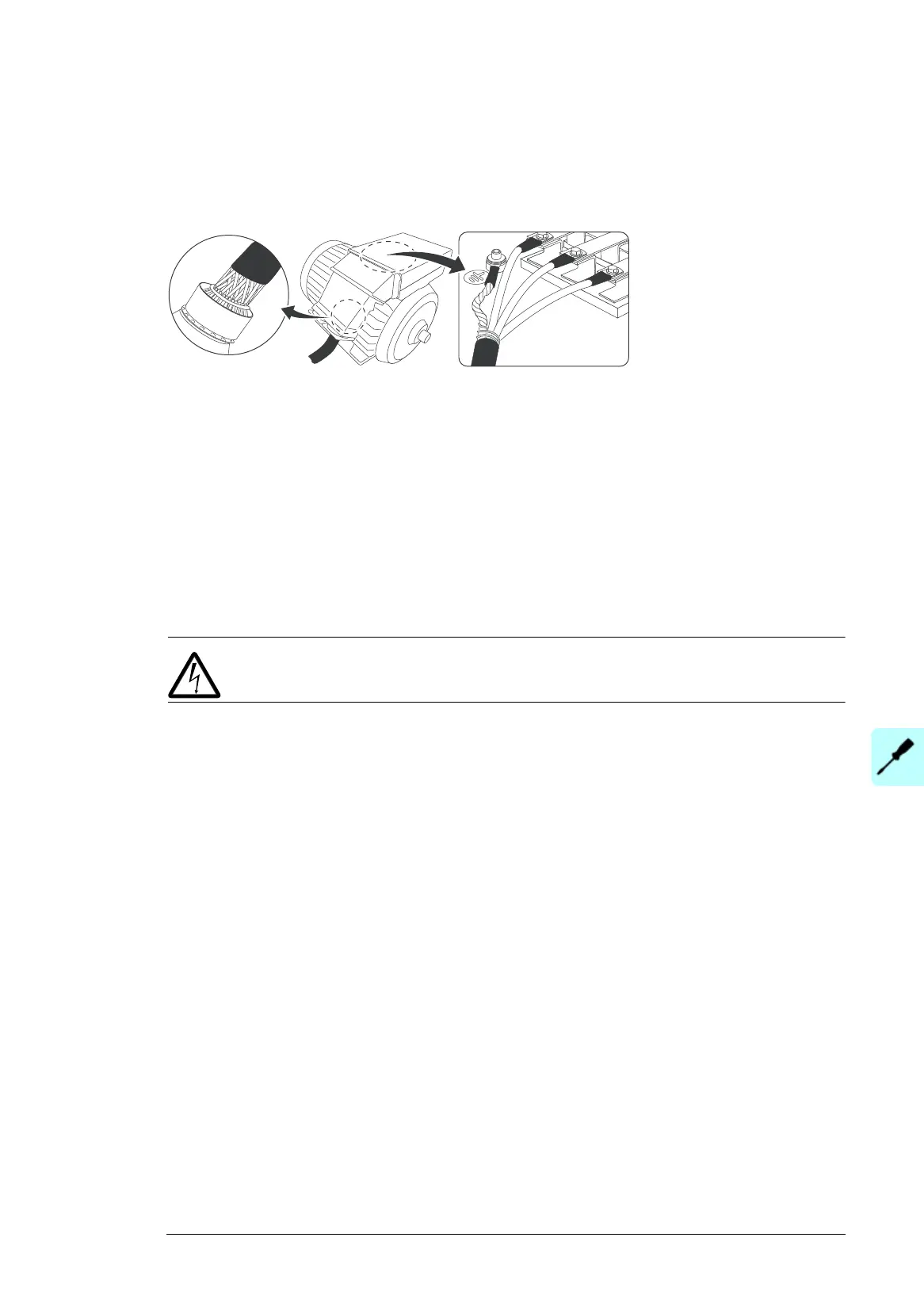
Grounding the motor cable shield at the motor end
Always ground the motor cable shield at the motor end. For minimum radio frequency
interference, ground the motor cable shield 360 degrees at the lead-through of the motor
terminal box
See also Continuous motor cable shield or enclosure for equipment on the motor cable on
page 57.
Connecting the control cables
See chapter Control unit on page 79 for the default I/O connections of ACS580 standard
control program. The default I/O connections can be different with some hardware options,
see the circuit diagrams delivered with the drive for the actual wiring.
Connect the cables as described under Control cable connection procedure on page 71.
Control cable connection procedure
WARNING! Obey the instructions in chapter Safety instructions. If you ignore
them, injury or death, or damage to the equipment can occur.
1. Stop the drive and do the steps in section Precautions before electrical work on page
16 before you start the work.
2. Run the control cables to the inside of the drive module cubicle as described in section
Grounding the outer shields of the control cables at the cabinet lead-through below.
3. Route the control cables as described in section Routing the control cables inside the
cabinet (frames R10 and R11) on page 74.
4. Connect the control cables as described in sections Connecting the control unit cables
on page 74 … Setting the voltage range of the auxiliary control voltage transformer
(T21) on page 76.

 Loading...


