Electrical installation 67
Connecting the power cables
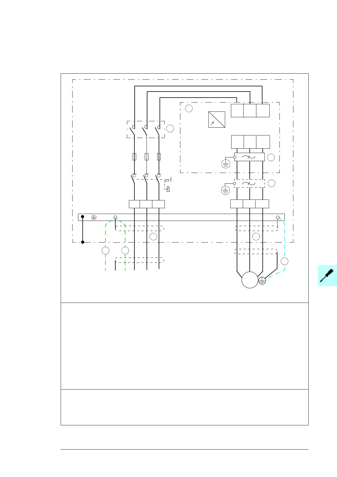
Connection diagram
1 Use a separate grounding PE cable (1a) or a cable with a separate PE conductor (1b) if the
conductivity of the shield does not meet the requirements for the PE conductor (see page 53).
2 360-degree grounding is recommended if shielded cable is used. Ground the other end of the input
cable shield or PE conductor at the distribution board.
3 360-degree grounding is required.
4 Line contactor (option +F250)
5 Common mode filter
6 du/dt filter (option +E205)
7 Use a separate grounding cable if the shield does not meet the requirements of IEC 61439-1 (see
page 53) and there is no symmetrically constructed grounding conductor in the cable (see page 54).
8Drive module
Note:
If there is a symmetrically constructed grounding conductor on the motor cable in addition to the conductive
shield, connect the grounding conductor to the grounding terminal at the drive and motor ends.
Do not use an asymmetrically constructed motor cable. Connecting its fourth conductor at the motor end
increases bearing currents and causes extra wear.
PE
ACS580-07
U1 V1 W1
U2
V2
W2
3
7
6
5
L1 L2 L3(PE) (PE)PE
~
~
L1 L2 L3
T1/ T2/ T3/
2
1b1a
L1
/
L2
/
L3
/
4
U1
V1
W1
U2 V2 W2
8
Q1
Q2
M
3
~

 Loading...


