4 Repair
4.5.2. Replacement of brake release unit
3HAC022033-001 Revision: K302
© Copyright 2004-2011 ABB. All rights reserved.
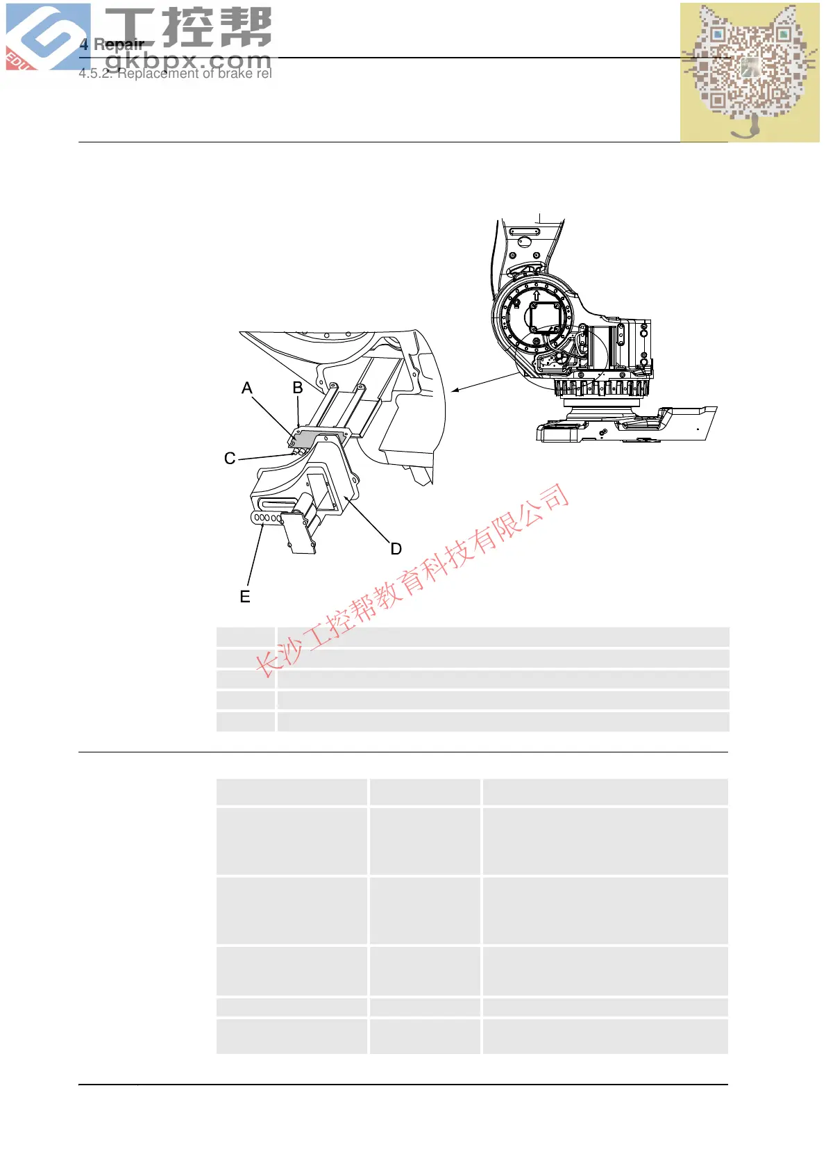
Location of brake release unit, frame
The later design includes a brake release unit with push buttons, placed together with the
SMB unit on the left hand side of the frame as shown in the figure below.
xx0200000226
Required equipment
A Brake release unit
B Attachment screws, brake release unit (4 pcs)
C Buttons
D SMB cover
E Push button guard
Equipment, etc. Spare part no. Note
Brake release circuit
without buttons, at base
3HAC14219-1 Brake release at the base, according to
figure Location of brake release unit, base
on page 301.
Includes brake release unit 3HAC14228-1.
Brake release circuit with
buttons, at base
3HAC12989-1 Brake release at the base, according to
figure Location of brake release unit, base
on page 301.
Includes brake release unit 3HAC16036-1.
Brake release unit with
buttons, at frame
3HAC16036-1 Brake release unit at the frame, according
to figure Location of brake release unit,
frame on page 302.
Push button guard 3HAC2744-1
Standard toolkit - Content is defined in section Standard
toolkit on page 427.
Continued
Continues on next page
 Loading...