2 Installation and commissioning
2.5.5. Manually releasing the brakes, external brake release unit
873HAC022033-001 Revision: K
© Copyright 2004-2011 ABB. All rights reserved.
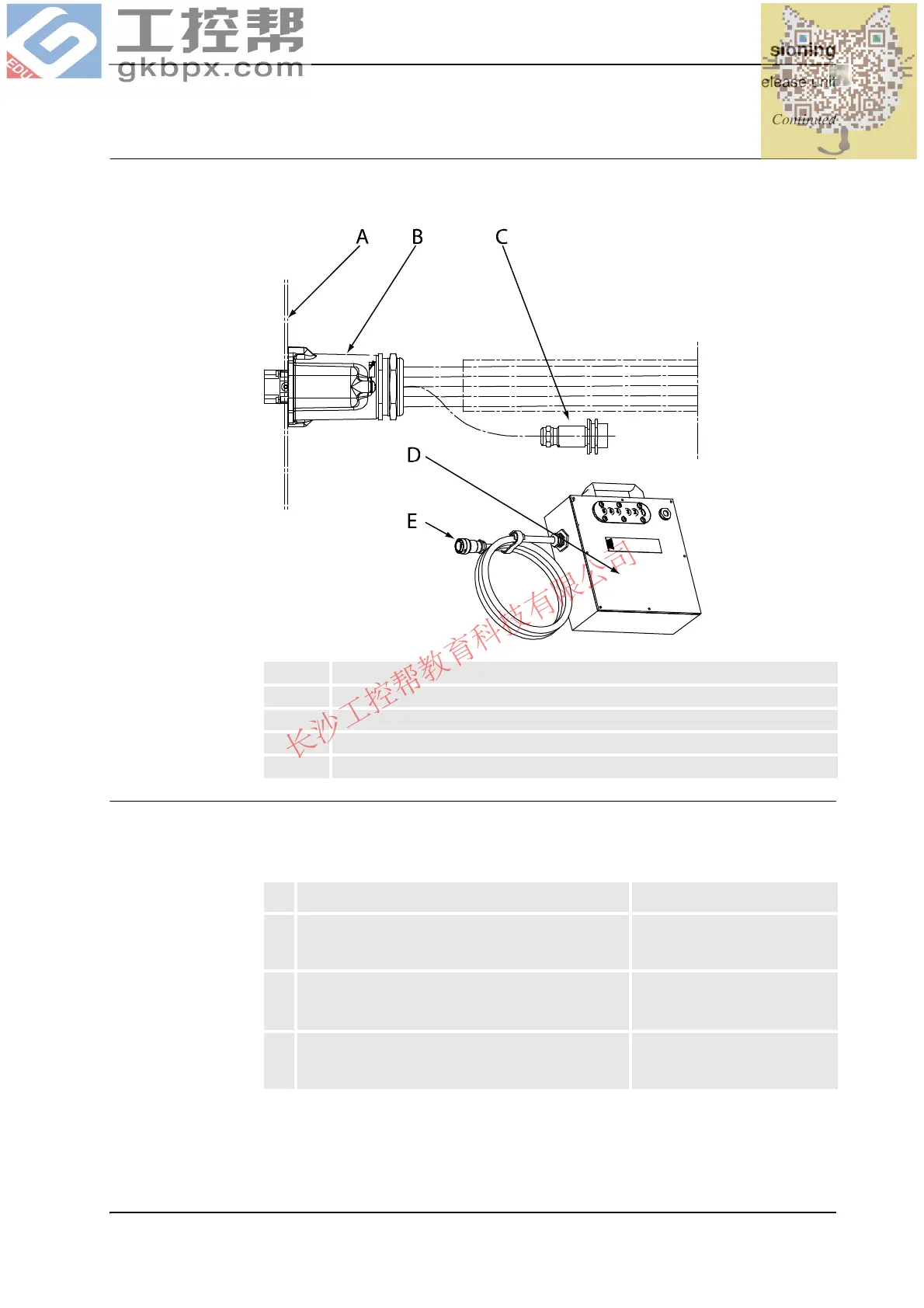
Connectors, external brake release unit
The illustration below shows the connectors on the robot and on the external brake release
unit.
xx0200000081
Releasing the brakes
This section describes how to release the holding brakes when the robot is equipped with an
external brake release unit.
A Rear connector plate
B Connector R1.MP
C Connector R1.BU
D External brake release unit
E Connect to R1.BU
Action Note
1. Remove the rear cover plate from the base of the
robot by unscrewing its attachment screws and plain
washers.
Shown in the figure Connec-
tions, robot on page 86.
2. Locate the free connector, connected to the rear of
connector R1.MP, behind the rear connector plate.
Make sure it is designated R1.BU.
Shown in the figure Connectors,
external brake release unit on
page 87.
3. Connect the external brake release unit to the
connector R1.BU.
Art. no. is specified in section
Required equipment on page
86.
Continued
Continues on next page
 Loading...