26 Operation basics and hardware description
1)
Interlocked. The front cover and the bottom cover can be removed and replaced only when the DC switch is
in position 0 (switched off). The covers can be removed separately.
2)
The cooling fan cools the heat sink and main circuit components. The stirring fan cools the control board.
3)
Control cable clamps (3 pieces), fixing screws M4x14 (6 pieces), allen key, inverter securing screw, second
PE Terminal. AC connector, DC connector sealing plugs.
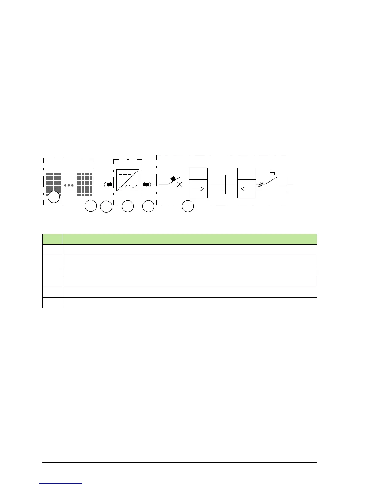
Single line diagrams of the system
Block diagram of single-phase photovoltaic (PV) system
The figure below shows the single-phase system configuration.
No. Description
1 Solar module/panel
2 String (array) of solar modules/panels
3 DC input (up to 4 parallel strings)
4 String inverter PVS300
5 AC output, single phase
6 AC distribution board
kWh
3 ~
kWh
1
2
3
5 64
1/N/PE AC 230 V 50 Hz
PVS300PV1 PVn
 Loading...


