66 Electrical installation
Connecting the control cables
See section Recommended AC output power cable types on page 38.
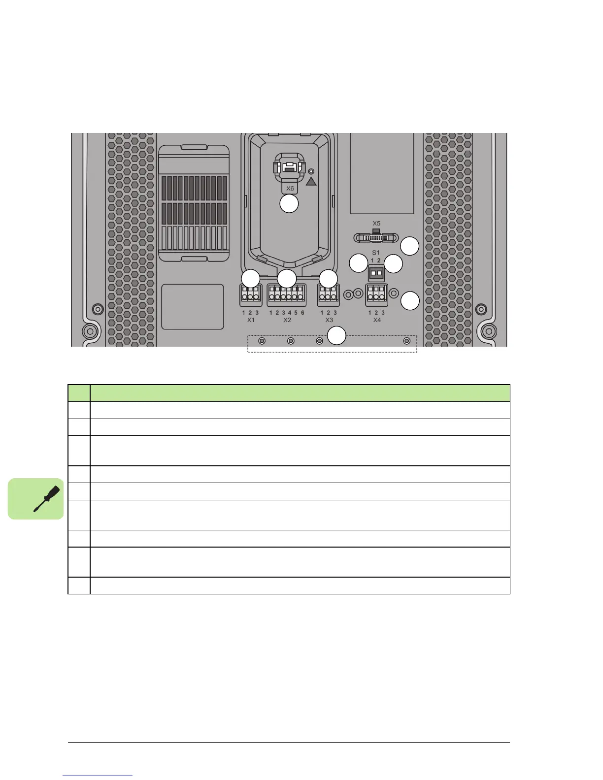
Connection area layout
Description
1 X1 spring terminal, programmable output relay interface for external control equipment.
2 X2 spring terminal, RS-485 interface for remotely installed control unit.
3 X3 spring terminal, RS-485 I2I interface for communication purposes between 3 inverters
in 3~ system.
4 X4 spring terminal, RS-485 embedded fieldbus interface.
5 X5 connector, for ABB Fieldbus adapters (not in use).
6 X6 RJ45 data type 8P8C plug connector, RS-485 Interface for local installation of Control
Unit or optional wireless transceiver.
7 S1:1 Selector switch, not in use, default always OFF.
8 S1:2 Selector switch for termination of embedded fieldbus at the end of the network by
switching ON, default OFF.
9 Nut inserts for clamp connectors used for connecting cable shields to protective earth.
 Loading...


