Operation 89
LED status indications
Graphical display
The graphical display is used to show:
• Operational status
• Menus which can be navigated by the user
• Performance monitoring
• Event messages (for example, faults, warnings, maintenance reminders)
• Help
Refer to chapter Start-up on page 77 for details of the settings which must be made
using the graphical display the first time the inverter is started up.
Refer to chapter Navigation map on page 125 for a map showing the inverter menu
hierarchy. The menu hierarchy includes: Start up assistant, Output view, and Menu
View.
The Help view appears when the Help (?) key is activated.
The Parameter view appears when parameter Edit is selected from Menu.
The Message view appears when an event, such as a fault, is activated.
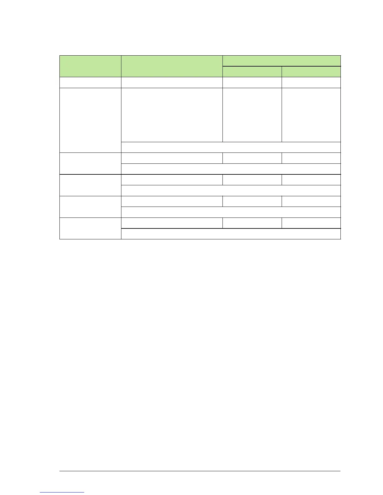
Status Control unit bi-colour LED
Control board LEDs
Dual colour LED Red fault LED
Going to sleep OFF OFF OFF
Fault ON Red ON Red (fault can
be reset)
Flashing Red
(requires DC and
AC disconnection
to reset)
ON only if there is
an active ground
fault
The inverter has an active fault requiring user action to reconnect to grid
Warning Flashing Red (1s ON, 2s OFF) Flashing Green OFF
The inverter has an active warning and is temporarily in stand-by mode
Stand-by Flashing Green (1s ON, 2s OFF) Flashing Green OFF
The inverter is in stand-by mode with no faults present
Limited operation Flashing Green (3s ON, 1s OFF) ON Green OFF
The inverter is in power feeding mode with limited power output
Normal operation ON Green ON Green OFF
The inverter is in power feeding mode
 Loading...


