58 Electrical installation
Routing the cables
General rules
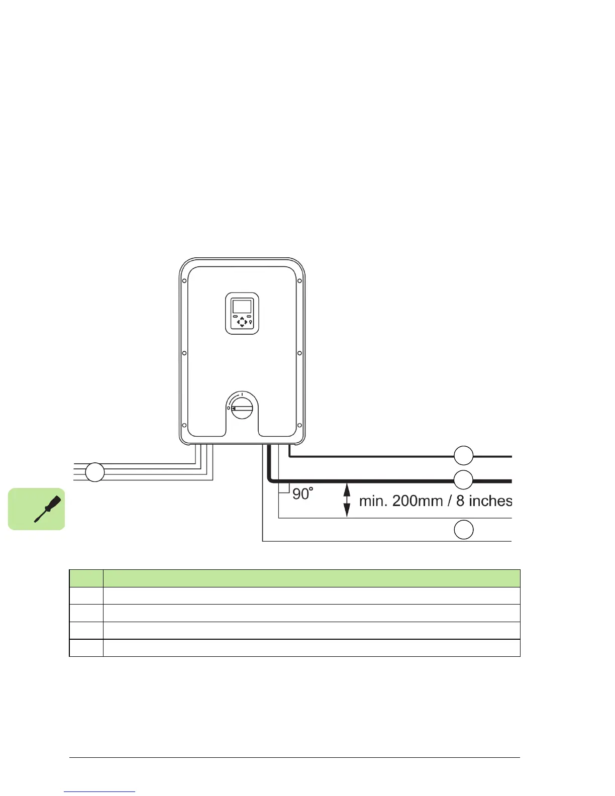
Ideally, the input, output and control cables should be installed on separate trays.
If control cables must cross over power cables, arrange them at an angle as near to
90 degrees as possible. Try to ensure that control cables and power cables (AC and
DC) are kept at least 20 cm (8 inches) apart. Do not run any cables behind the
inverter.
Metal cable trays must be electrically bonded to each other and to the grounding
electrodes. Aluminium tray systems can be used to improve local equalizing of
potential.
Checking the insulation of the assembly
Note: The inverter always measures the impedance between the DC terminals and
ground before establishing a grid connection. If the impedance is less than 900 kΩ, a
No. Cable type
1 DC input cables
2 PE cable
3 AC output cable
4 Control cables
 Loading...


