30 Operation basics and hardware description
User interface and communication features
AC Short circuit protection In case of external AC side short circuit, the inverter trips to
protect its electronics.
Over temperature
protection
If the inverter detects potentially harmful internal temperatures, it
shall temporarily limit output power by changing the DC operating
point. If the internal temperature rises towards dangerous limits,
power conversion and grid connection is interrupted.
Feature Description/Operation
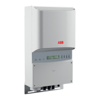
Control unit The inverter has a detachable control unit which can be installed
remotely, either with a wired connection or a wireless link. The
control unit has a graphical display and straightforward keypad
with dedicated help key. The software functions are intuitive
including comprehensive system monitoring, setup assistance
and help menus for the user. The control unit can be operated 24
hours per day.
Inverter to inverter
communication link (I2I
link)
A (hard wired) serial communication link between three PVS300
inverters, each feeding into separate phases. The I2I link enables
inverters to share monitored information and is the basis for the 3-
phase monitoring function.
Three phase configuration
and monitoring
With help of I2I link, three PVS300 inverters can be connected to
three separate phases to form a photovoltaic (PV) system which
has three phase AC grid connection and monitoring. In this
configuration the power output difference between phases can be
limited to a specific kVA value.
Status LEDs The inverter has green and red LEDs which show the operational
status in addition to information provided by display. The control
unit has one green/red LED. If the control unit is remotely installed
the LEDs mounted on the inverter control board are visible for the
user.
Relay output The inverter has an electrically isolated relay output. The inverter
software includes pre-programmed functions from which the user
can select the most suitable for the system. The relay output can
indicate the inverter’s grid connection or fault status, or it can be
used to control building load circuits based on the inverter’s
current output level. The output signal can be externally
monitored or it can command external equipment.
Embedded fieldbus
interface
A (hard wired) serial communication link supporting Modbus RTU
protocol. The EFB interface is used to establish communication
between the inverter and an external monitoring or control system
(for example, ABB remote monitoring adapter SREA-50).
Feature Description/Operation
 Loading...


