28 Operation basics and hardware description
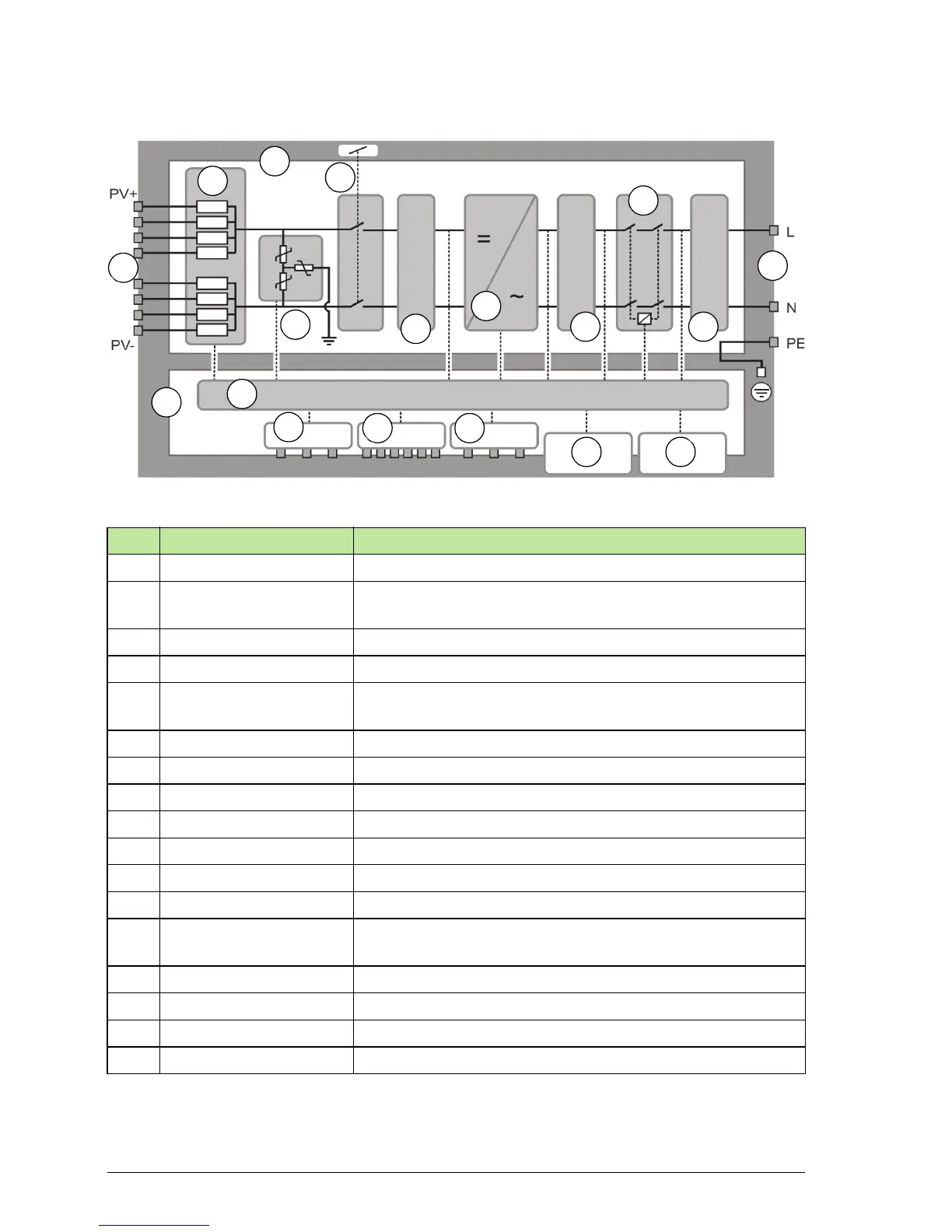
PVS300 block diagram
No. Component Description
1 DC terminals Connection of DC cabling from solar arrays
2 Main board Integrated circuit board onto which the main circuit
components are attached
3 String fuses Short circuit protection for string circuits
4 Surge protection device Voltage peak protection
5 DC switch Main on/off switch of the inverter (interlocked with front and
bottom covers)
6 EMI filter Attenuation of electromagnetic interference
7 Inverter DC to AC conversion
8 LCL filter Suppression of AC voltage distortion and current harmonics
9 AC contactor Switching of AC load current
10 AC terminals Connection of AC cabling
11 Control board Controls and interfaces to the inverter
12 Control and monitoring Control and monitoring circuits
13 Programmable relay
output
Relay contacts for controlling external devices
14 I2I link Inverter to inverter interface
15 Monitoring interface Performance monitoring
16 Control unit Removable control unit
17 Status LEDs Inverter status LEDs, behind the control unit
1
5
6
3
2
4
7
8
9
11
10
6
12
14 15
16 17
13
 Loading...


