32 Operation basics and hardware description
Optional accessories
Connections and control interfaces
See the Connection diagram on page 60.
DC input connectors
DC input connectors are the connection point for solar panels. The inverter has four
pairs of DC+ and DC- connectors to attach up to four separate strings of solar panels.
Each string is connected to one pair of DC connectors. Correct polarity is assured by
using different connector types for DC+ and DC-.
AC connector
The AC connector is the connection point to the low voltage AC grid. AC power flows
through this connector.
Relay output terminal X1
X1 is the connection point for control signal to external system or device. This
terminal is electrically isolated (voltage free).
Remote control unit terminal X2
X2 is the connection point for RS-485 transmission line to the remote control unit
installation kit PVS-APK-F. For more details, see PVS-APK-F control unit wall
mounting kit for PVS300 string inverters installation guide (3AUA0000108440
[English]).
I2I link terminal X3
X3 is the connection point for the RS-485 transmission line between three PVS300
inverters.
Embedded fieldbus terminal X4
X4 is the connection point for the daisy-chained RS-485 transmission line with one
master and multiple slaves. The X4 terminal has a built-in selector switch for
transmission line termination purposes.
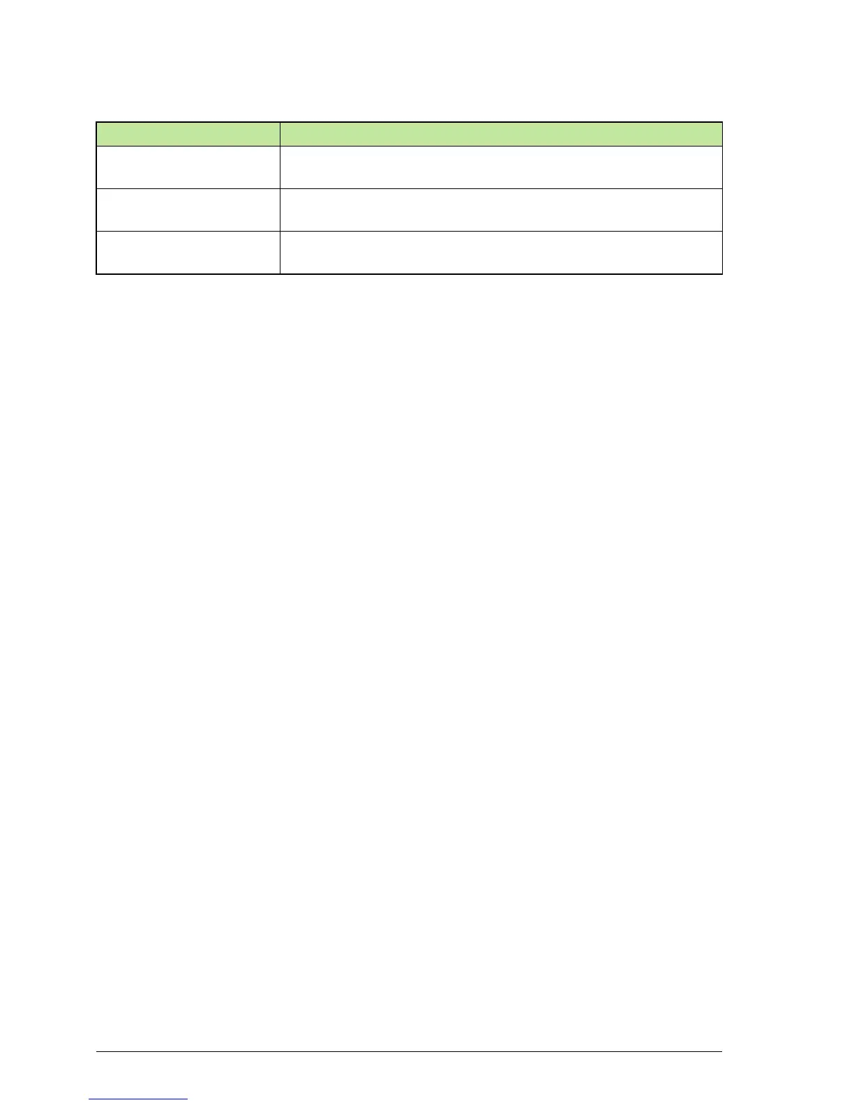
Type designation Description
SREA-50 Remote monitoring adapter with data logger, Ethernet port and
integrated Web-browser based graphical user interface.
PVS-APK-F Fixed control unit wall mounting kit including flush and surface
mounting frames and cabling adapters.
PVS-APK-M Mobile control unit mounting kit including communication
transceivers, power source and table stand.
 Loading...


