82 Start-up
Setting up the embedded fieldbus interface for remote monitoring
The node addresses need to match the slave addresses with which the monitoring
system communicates.
From Menu
-
>
Communication
-
>
Embedded Fieldbus, set the following parameters:
58.01 Protocol enable. 0=none, 1=Modbus RTU.
58.03 Node address. Set the inverter's node address. Two inverters with the same
address are not allowed on-line. Do not use address value 0 or values above 247. For
example, if there are 9 inverters in the system then set node addresses from 01...09.
Setting up the relay output
Select the status information that the relay output indicates. From Menu
-
>
Communication
-
>
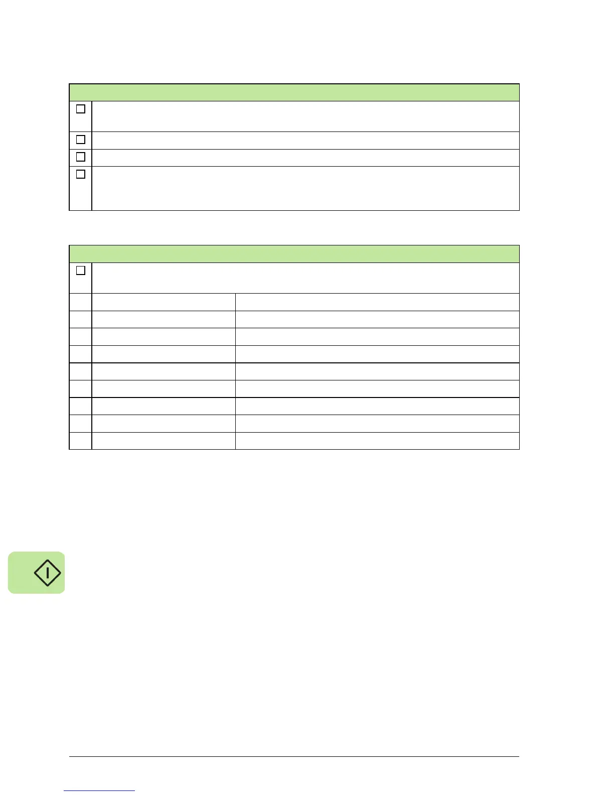
Relay output, select the desired status information:
Relay output source Status information that the relay output indicates
[0] Off Off (Relay output is not in use)
[1] Fault Fault
[2] No fault No fault
[3] Grid connected Grid connected
[4] Grid not connected Grid not connected
[5] Power level 20% Output power level over 20% of rated power
[6] Power level 40% Output power level over 40% of rated power
[7] Power level 70% Output power level over 70% of rated power
 Loading...


