84 Operation
The inverter’s main user interface is a control unit, featuring buttons, LEDs and an
LCD graphical display. Additionally, there are status LEDs on the inverter control
board which can be seen when the control unit is removed.
For information on the use of the panel, see chapter Navigation map on page 125.
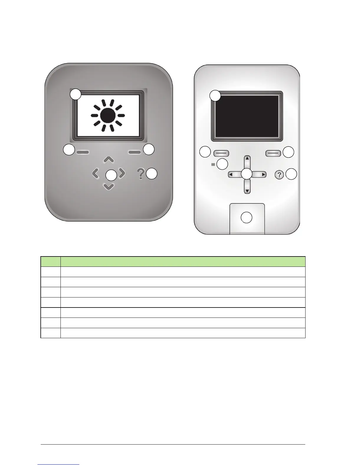
No. Description
1 Graphical display
2 Left softkey
3 Right softkey
4 Status LED, dual color green or red
5 Up/Down/Left/Right arrow keys
6 Help key
7 USB connector and lid (for use by service only)
1
2
5
6
7
3
Front cover on
Front cover off
6
5
4
2
3
1
 Loading...


