TPU2000/2000R Modbus/Modbus Plus Automation Guide
103
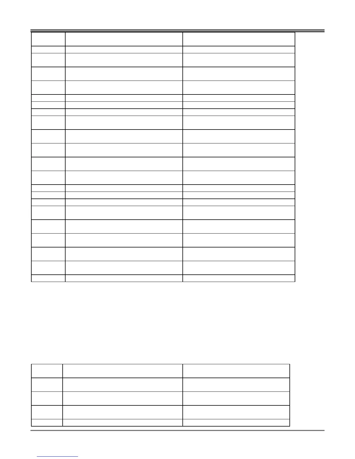
Register
Address
Item Description
Month 00<= Range <= 12
40945 Minimum Demand KVAR Hours (Phase B)
Day
Most Significant Byte 8 Bits
00<= Range<= 31
40945 Minimum Demand KVAR Hours (Phase B)
Hour
Most Significant Byte 8 Bits
00<= Range <= 23
40946 Minimum Demand KVAR Hours (Phase B)
Minute
Most Significant Byte 8 Bits
00<= Range <= 59
40946 Reserved Byte Reserved
40947 KVAR Hours (Phase C) Minimum Demand Signed 32 Bit High Order Word MSW
40948 KVAR Hours (Phase C) Minimum Demand Signed 32 Bit Low Order Word LSW
40949 Minimum Demand KVAR Hours (Phase C)
Year
Most Significant Byte 8 Bits
00<= Range <= 99
40949 Minimum Demand KVAR Hours (Phase C)
Month
Least Significant Byte 8 Bits
00<= Range <= 12
40950 Minimum Demand KVAR Hours (Phase C)
Day
Most Significant Byte 8 Bits
00<= Range<= 31
40950 Minimum Demand KVAR Hours (Phase C)
Hour
Most Significant Byte 8 Bits
00<= Range <= 23
40951 Minimum Demand KVAR Hours (Phase C)
Minute
Most Significant Byte 8 Bits
00<= Range <= 59
40951 Reserved Byte Reserved
40952 KVAR Hours (3 Phase) Minimum Demand Signed 32 Bit High Order Word MSW
40953 KVAR Hours (3 Phase) Minimum Demand Signed 32 Bit Low Order Word LSW
40954 Minimum Demand KVAR Hours (3 Phase)
Year
Most Significant Byte 8 Bits
00<= Range <= 99
40954 Minimum Demand KVAR Hours (3 Phase)
Month
Least Significant Byte 8 Bits
00<= Range <= 12
40955 Minimum Demand KVAR Hours (3 Phase)
Day
Most Significant Byte 8 Bits
00<= Range<= 31
40955 Minimum Demand KVAR Hours (3 Phase)
Hour
Most Significant Byte 8 Bits
00<= Range <= 23
40956 Minimum Demand KVAR Hours (3 Phase)
Minute
Most Significant Byte 8 Bits
00<= Range <= 59
40956 Reserved Byte Reserved
Breaker Counters (11 Registers Defined) Modbus Function 03 Read Only
Breaker Counters allow diagnostic evaluation of operations for maintenance purposes The TPU2000/2000R
allows selection of reclosure for up to 4 shots with the fifth event initiating lockout. The counter registers are reset
via a write to registers 63713 through 63719 as defined in Table 5-25. Table 5-25 defines the register map for the
Breaker Counter capabilities within the unit. Additionally, unreported fault record counts are available. This is
especially helpful when accessing fault buffers (using the unreported records command) and knowing the amount
of records yet to be accessed.
Table 5-25. Breaker Counter Definition Table
Register
Address
Item Description
41025 Unreported Differential Fault Record
Counter
Unsigned Integer 16 Bits
0<=Range<=9999
41026 Unreported Through Fault Record Counter Unsigned Integer 16 Bits
0<=Range<=9999
41027 Unreported Harmonic Restraint Record
Fault Counter
Unsigned Integer 16 Bits
0<=Range<= 9999
41028 Unreported Operation Record Counter Unsigned Integer 16 Bits
 Loading...