TPU2000/2000R Modbus/Modbus Plus Automation Guide
147
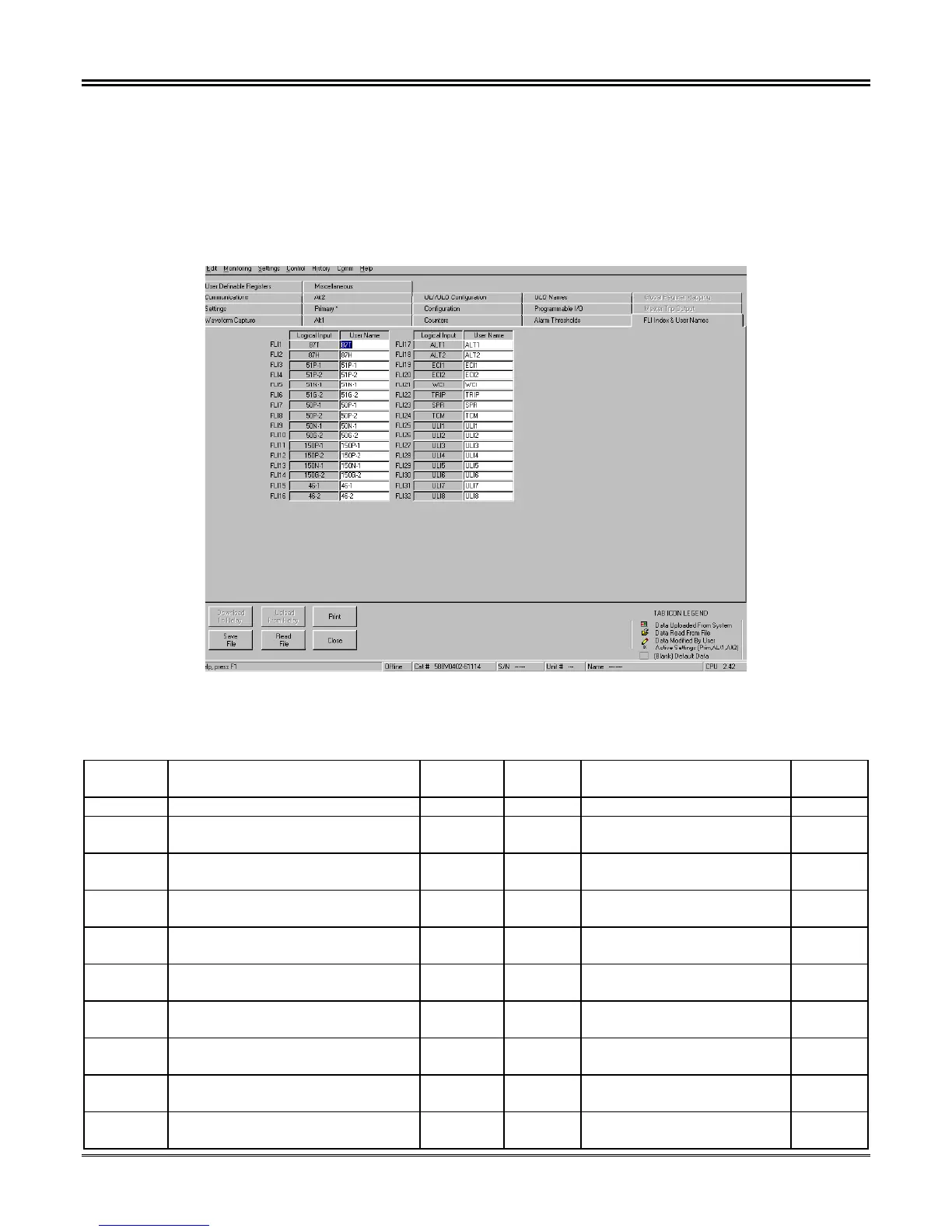
3. The default list corresponds to the Logical Input mapping of Logical Inputs (hereto referred as LI) as
illustrated in Table 5-47.
4. If one would wish to change the relay protective function element mapped to the specific LI, depress
the “ENTER” key. The display in Figure 5-55 shall result.
5. The user would then scroll down the list and highlight the element desired to be mapped to the
specific LI within the edited list.
6. Depress the “ENTER” key to map the selected element into the table.
Figure 5-54. ECP Default Logical Input List
Table 5-47. ECP Default Correlation to Forced Logical Input Bit Map
FLI
Number
Description User
Name
FLI
Number
Description User
Name
FLI 01 3 Phase % Diff. Current Control 87 T FLI 17 Alternate Settings 1 Enable ALT 1
FLI 02 3 Phase Inst. Differential Current
Control
87H FLI 18 Alternate Settings 2 Enable ALT 2
FLI 03 Winding 1 Phase Time
Overcurrent Control
51P-1 FLI 19 Event Capture Initiate 1 ECI 1
FLI 04 Winding 2 Phase Time
Overcurrent Control
51P-2 FLI 20 Event Capture Initiate 2 ECI 2
FLI 05 Winding 1 Neutral Time
Overcurrent Control
51N-1 FLI 21 Waveform Capture Initiate WCI
FLI 06 Winding 2 Ground Time
Overcurrent Control Winding 2
51G-2 FLI 22 Differential Trip Output
Contact Enable
TRIP
FLI 07 Phase Instantaneous Level 1
Enable Winding 1
50P-1 FLI 23 Sudden Pressure SPR
FLI 08 Phase Instantaneous Level 1
Enable Winding 2
50P-2 FLI 24 Trip Coil Monitor Enable TCM
FLI 09 Neutral Instantaneous Level 1
Enable Winding 1
50N-1 FLI 25 User Logical Input 1 ULI 1
FLI 10 Ground Instantaneous Level 1
Enable Winding 2
50G-2 FLI 26 User Logical Input 2 ULI 2
 Loading...