TPU2000/2000R Modbus/Modbus Plus Automation Guide
63
Discrete
Address
Item Description
01048 OUT 4 Physical Output Contact 4 Change Detect Between Scans
01049 OUT 3 Physical Output Contact 3
01050 OUT 3 Physical Output Contact 3 Change Detect Between Scans
01051 OUT 2 Physical Output Contact 2
01052 OUT 2 Physical Output Contact 2 Change Detect Between Scans
01053 OUT 1 Physical Output Contact 1
01054 OUT 1 Physical Output Contact 1 Change Detect Between Scans
01055 TRIP Status Breaker Trip Physical Output Contact
01056 TRIP Momentary Breaker Trip Physical Output Contact Change Detect Between Scans
1X Discrete Contact Inputs
Discrete physical input and relay element status are available via a function 02 request through Modbus and
through a Modbus Plus Host. The TPU2000/2000R does not support the Modbus Plus feature of PEER COP
thus 1X data cannot be obtained from a PLC (Programmable Logic Controller) supporting such a feature. Figure
5-19 illustrates a typical command sequence. The Host polls the TPU2000R for the Data. The TPU2000R
receives the request and responds with the expected data. The Host then interprets the command response,
checks the LRC checksum in ASCII mode and then displays the interpreted data. If the node is configured for
RTU Modbus, the start of message character is three character delays, and the end of message consists of a
CRC-16 checksum and three character delays. Additional information is available in Modicon’s protocol manual
references listed at the beginning of this document. The same information is available through a 4X register read
command, which allows a host without 1X data accesses capabilities to obtain physical input and relay element
information. Tables 5-5 through 5-9 list the 1X discrete contact memory map as defined for Modbus RTU and
ASCII. Modbus Plus embeds the Modbus message in its structure. Please reference Section 5 of this document
for a more complete discussion of Modbus Plus message structure.
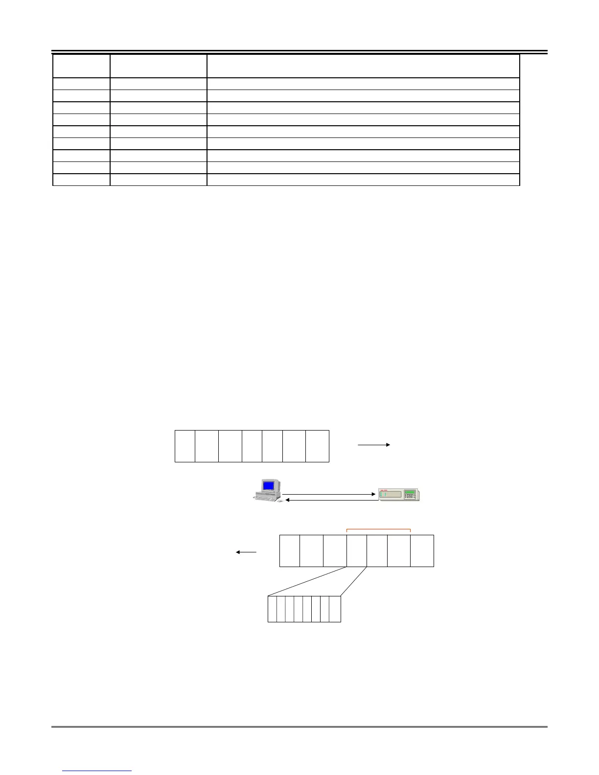
Function Code 2 - Read Input Status (Read Only Data)
Figure 5-19 illustrates the command format required for execution of function code 2.
Modbus Host
Modbus Slave Addr =1
Read from
1X Mapping
Slave
Addr.
Funct.
Code
02
Start
Addr
HI
Start
Addr
LO
Coils
Read
HI
Coils
Read
LO
Error
Check
EOM
SOM
Slave
Addr.
Funct.
Code
02
Byte
Count
*
Data
Byte
1
…..
Data
Byte
NNN
Error
Check
EOM
SOM
Byte 1 …2……..3…….4…….5……6……..7….
MSB LSB
87
65
4321
SOM = Start of
Message Header
EOM = End of
Message Header
E
C
Figure 5-19. 1X Input Request Using Modbus Command 02
It should be noted that every TPU2000R allows real time status reporting when the unit is polled. If a status is
momentary and is missed during the host poll, then the data is lost. Polling using the status Momentary Change
Detect Feature insures that the host device does not miss the momentary change. It should also be noted that
data requested from 1X data address ranges not defined within this document generates Modbus exception
codes.
 Loading...