TPU2000/2000R Modbus/Modbus Plus Automation Guide
13
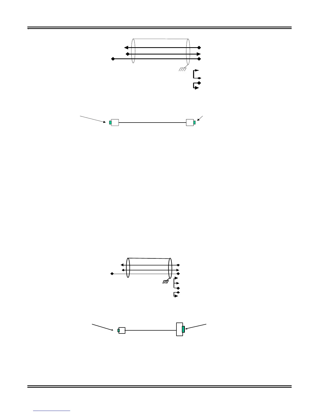
Protective Relay PC
2 Receive Data
3 Transmit Data
3 Transmit Data
2 Receive Data
5 Ground
5 Ground
1 Data Carrier Detect
6 Data Set Ready
4 Data Terminal Ready
7 Request To Send
8 Clear To Send
No connection
9 Ring Indicator
9 pin D shell
Male Connector
9 pin D shell
Female Connector
DTE
DTE
Figure 3-3. 9 Pin RS232-DTE-DTE Connector
An RS232 interface was designed to simplify the interconnection of devices. Definition of terms may demystify
issues concerning RS232 interconnection. Two types of RS232 devices are available, DTE and DCE. DTE
stands for Data Terminal Equipment whereas DCE stands for Data Communication Equipment. These definitions
categorize whether the device originates/receives the data (DTE) or electrically modifies and transfers data from
location to location (DCE). Personal Computers are generally DTE devices while line drivers/ modems/ converters
are DCE devices. DPU/TPU/GPU devices have RS232 DTE implementation. Generally, with a few exceptions, a
“straight through cable”(a cable with each pin being passed through the cable without jumpering or modification)
will allow a DTE device to communicate to a DCE device.
Connection of a PC to a TPU2000 or TPU2000R requires cable modification since the interconnected devices are
both DTE. The same cabling would be utilized if one would connect two DCE devices. The classifications of
DTE/DCE devices allow the implementers to determine which device generates the signal and which device
receives the signal. Studying Figure 3-3, Pins 2 and 3 are data signals, pin 5 is ground whereas pins 1,6,7,8,9 are
control signals. The arrows illustrate signal direction in a DTE device. The TPU2000 and TPU2000R series of
protective devices do not incorporate hardware or software “handshaking”.
If a host device has an RS232 physical interface with a DB 25 connector, reference Figure 3-5 for the correct
wiring interconnection.
Protective Relay PC
2
Receive Data
3 Tra nsm it Da ta
3
Transmit Data
2 R eceive Da ta
5
Groun d
5 Groun d
8 D ata Ca rrier D ete ct
6 D ata Set Re ad y
20 D ata Termina l Ready
4 R equ est To Sen d
5 C le ar To S end
N o connection 2 2 R ing Indica tor
9 pin D she ll
Male Connector
25 pin D sh ell
Male Connector
DTE DTE
Figure 3-4. Connection of a DB 25 Connector to a TPU2000 or TPU2000R
 Loading...