TPU2000/2000R Modbus/Modbus Plus Automation Guide
7
commands on a HDLC- like protocol using a current injection interface. The discussion of Modbus
Plus protocol is included in this document. Only the TPU 2000R has the capability of communicating
using the Modbus Plus protocol. Please reference the TPU2000 and TPU2000R Modbus/Modbus Plus
Automation Technical Guide TG 7.11.1.7-51 for a discussion of this protocol. (AVAILABLE ON THE
TPU2000R ONLY).
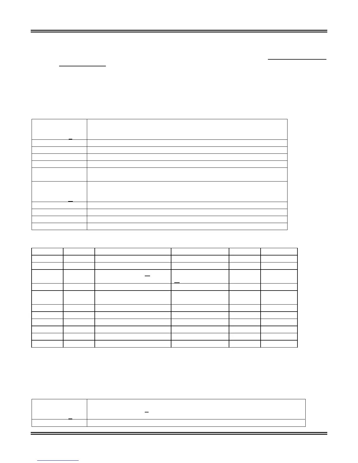
The device configuration for the TPU2000 is illustrated in Tables 2-1 and 2-2 illustrating the configuration options.
The generic part number for the TPU2000 is 4 8 8 M R X D Z – C S S S Q. Deciphering the part numbers: found
on the labels of the unit or obtained through ECP or the Front Panel LCD Interface, allows easy identification of
the communication options found on the unit.
Table 2-1. TPU2000 Communication Options
IF PART
NUMBER
POSITION “Z” IS
THE TPU2000 HAS AN INSTALLED OPTION
For unit 4 8 8 M R X D Z – C S S S Q
(COMMUNICATION PHYSICAL INTERFACE OPTION)
1 RS232 (COM 3) Isolated Port Enabled
2 RS485 (AUX COM PORT) and RS232 (COM 3) Ports Enabled
3 INCOM (AUX COM PORT) Enabled
4 RS 485 AUX COM PORT and INCOM (AUX COM PORT) Enabled
5 RS485 (AUX COM PORT) Ports Enabled
IF PART
NUMBER
POSITION “Q” IS
THE TPU2000 HAS AN INSTALLED OPTION
For unit 4 8 8 M R X D C – Z S S S Q
(COMMUNICATION PHYSICAL INTERFACE OPTION)
0 STANDARD TEN BYTE
1 DNP 3.0
2 SPACOM
4 MODBUS
Table 2-2. TPU2000 Communication Card Matrix for Unit 4 8 8 M R X D Z – C S S S Q
“Z” Digit “Q” Digit COM 3 AUX COM RS485 INCOM IRIG B
1 0 Standard 10 Byte RS232
2 0 Standard 10 Byte RS232 Standard 10 Byte Available
2 1 Standard 10 Byte or
DNP 3.0 RS232
Standard 10 Byte
or
DNP 3.0
2 2 Standard 10 Byte RS232 SPACOM
2 4 Standard 10 Byte or
Modbus RS232
Standard 10 Byte
or Modbus
Available
3 0 Available Available
4 0 Standard 10 Byte Available Available
4 1 DNP 3.0 Available Available
4 2 SPACOM
4 4 Modbus Available Available
5 0 Standard 10 Byte
The device configuration for the TPU2000R is illustrated in Tables 2-3 and 2-4 illustrating the configuration
options. The generic part number for the TPU2000 is 5 8 8 X X X Y Z – X X X X Q. Deciphering the part numbers:
found on the labels of the unit or obtained through ECP or the Front Panel LCD Interface, allows easy
identification of the communication options found on the unit.
Table 2-3. TPU2000R Communication Options
IF PART
NUMBER
POSITION “Y
” IS
THE TPU2000R HAS AN INSTALLED OPTION
For unit 5 8 8 X X X Y
Z – X X X X Q (X = Don’t Care)
(FRONT PANEL INTERFACE OPTION)
0 Horizontal Unit Mounting – No front panel LCD interface.
 Loading...