32 Rockwell Automation Publication 1734-UM018D-EN-E - September 2017
Chapter 4 Configure the Adapter for Direct Connection in RSLogix 5000 or Logix Designer Software
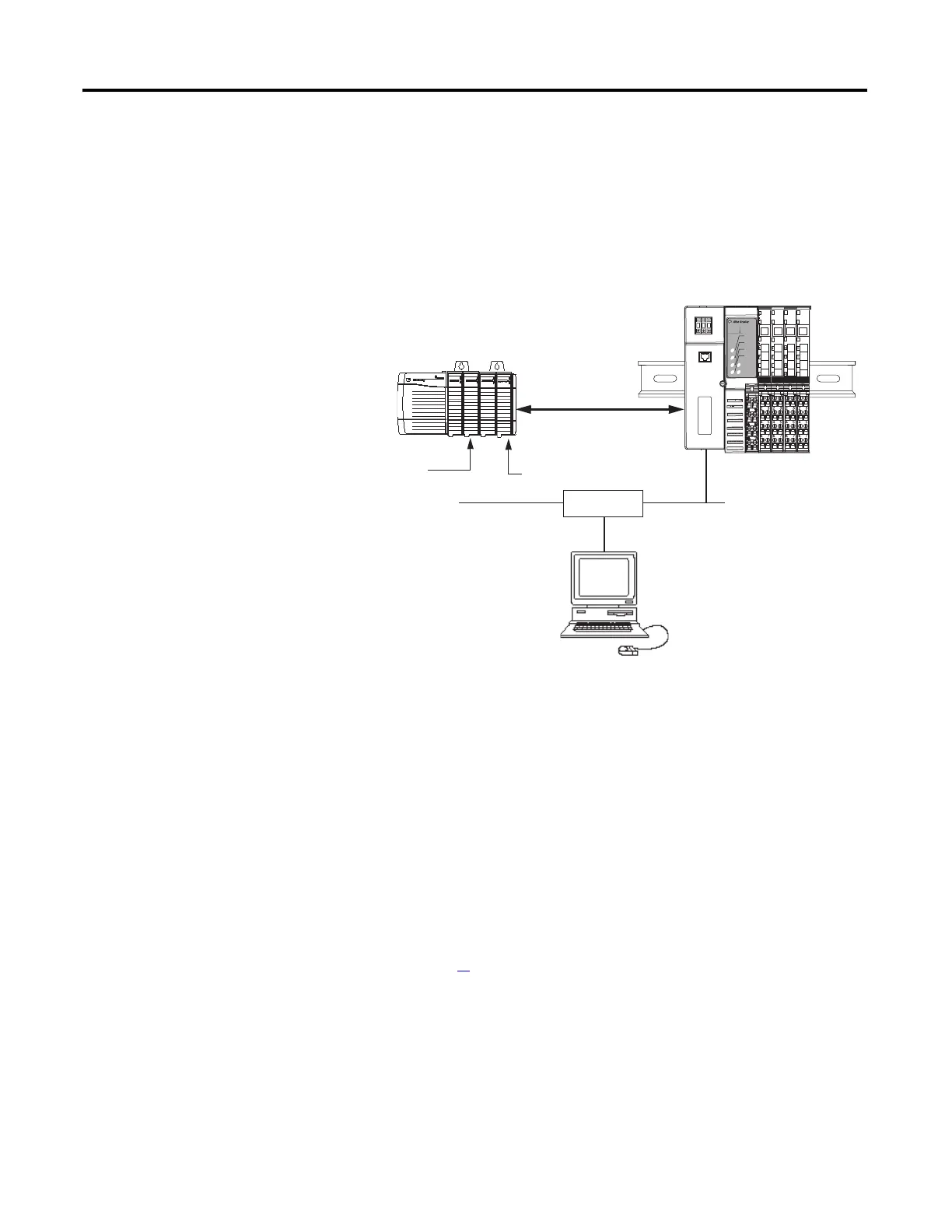
Set Up the Hardware
The following section describes how to set up the I/O Hardware.
In this example, a ControlLogix chassis contains the L63 controller in slot 1 and a
1756-ENBT bridge module in slot 3. The 1734-AENT adapter is mounted on a
DIN rail in slot 0, with a 1734-OW2/C relay output module in slot 1, a 1734-
OV4E/C sink output module in slot 2, and a power supply (not shown).
To work along with this example, set up your system as shown in the figure.
• In the example application, we assume that the L63 controller and
1756-ENBT module (firmware revision 4.006, or later) are in the slots
shown in the figure.
• Verify the IP addresses for your programming terminal, 1756-ENBT
module, and adapter.
• Verify the position (slot) of the I/O modules on the DIN rail.
• Verify that you connected all wiring and cabling properly.
• Be sure you configured your communication driver (for example,
AB_ETH-1 or AB-ETHIP-1) in RSLinx software, as described in
Appendix C
in this manual.
Local
chassis
POINT I/O
L63
controller (slot 1)
1756-ENBT
10.88.70.4 (slot 3)
Data
Switch
10.88.70.26
Programming
terminal
Slot 0 1 2 3
1734-AENT
10.88.70.2
Slot 0 1 2 3 4
02
0
1734-AENT Series B
Module
Status
Network
Activity
Network
Status
Point Bus
Status
System
Power
Field
Power
POINT I O
IP ADDRESS

 Loading...