56 Rockwell Automation Publication 1734-UM018D-EN-E - September 2017
Chapter 5 Configure the Adapter for Direct Connection, Rack Optimization, and Enhanced Rack Optimization in RSLogix 5000 or Logix Designer Software
Set Up the Hardware
The following section describe how to set up the I/O Hardware.
Set Up the POINT I/O Hardware
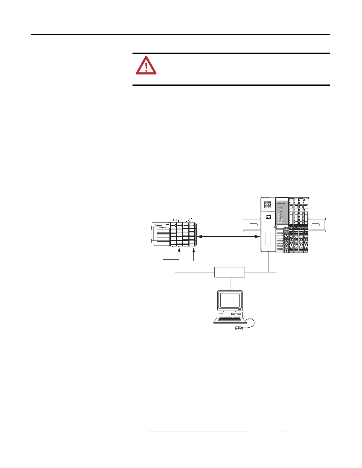
In this example, a ControlLogix chassis contains the L63 controller in slot 1 and a
1756-ENBT bridge module in slot 3. In this example, we mounted the
1734-AENT adapter on a DIN rail in slot 0, with a 1734-OW2/C relay output
module in slot 1, a 1734-OV4E/C sink output module in slot 3, and two other
POINT I/O modules which will not be controlled by this Logix controller in
slots 2 and 4.
To work along with this example, set up your system as shown in the figure.
• Note that in the example application, the Logix controller and
1756-ENBT module (firmware revision 4.006 or later) we assume are in
the slots shown in the figure.
• Verify the IP addresses for your programming terminal, 1756-ENBT
module, and I/O adapter.
• Verify the position (slot) of the I/O modules on the DIN rail.
• Verify that you properly connected all wiring and cabling.
• Make sure you configured your communication driver (such as
AB_ETH-1 or AB-ETHIP-1) in the RSLinx software. See Configure the
RSLinx Ethernet Communication Driver in Appendix C.
ATTENTION: You must only use Series C and above POINT I/O modules
with 1734-AENT EtherNet/IP Adapters. Series A or Series B POINT I/O
modules do not work with 1734-AENT EtherNet/IP Adapters (does not
apply to POINTGuard modules).
Local
chassis
POINT I/O
L63
controller (slot 1)
1756-ENBT
10.88.70.4 (slot 3)
Data
Switch
10.88.70.26
Programming
terminal
Slot 0 1 2 3
1734-AENT
10.88.70.2
Slot 0 1 2 3 4
02
0
1734-AENT Series B
Module
Status
Network
Activity
Network
Status
Point Bus
Status
System
Power
Field
Power
POINT I O
IP ADDRESS

 Loading...