30 Rockwell Automation Publication 22C-UM001J-EN-E - January 2017
Chapter 1 Installation/Wiring
(6) Common for Analog Input 2 (AI2). Electronically isolated from digital I/O and opto output. Not to be used with Analog Input 1
(AI1), Analog Output 1 (AO1) or Analog Output 2 (AO2). With Analog Input 2, provides one fully isolated analog input channel.
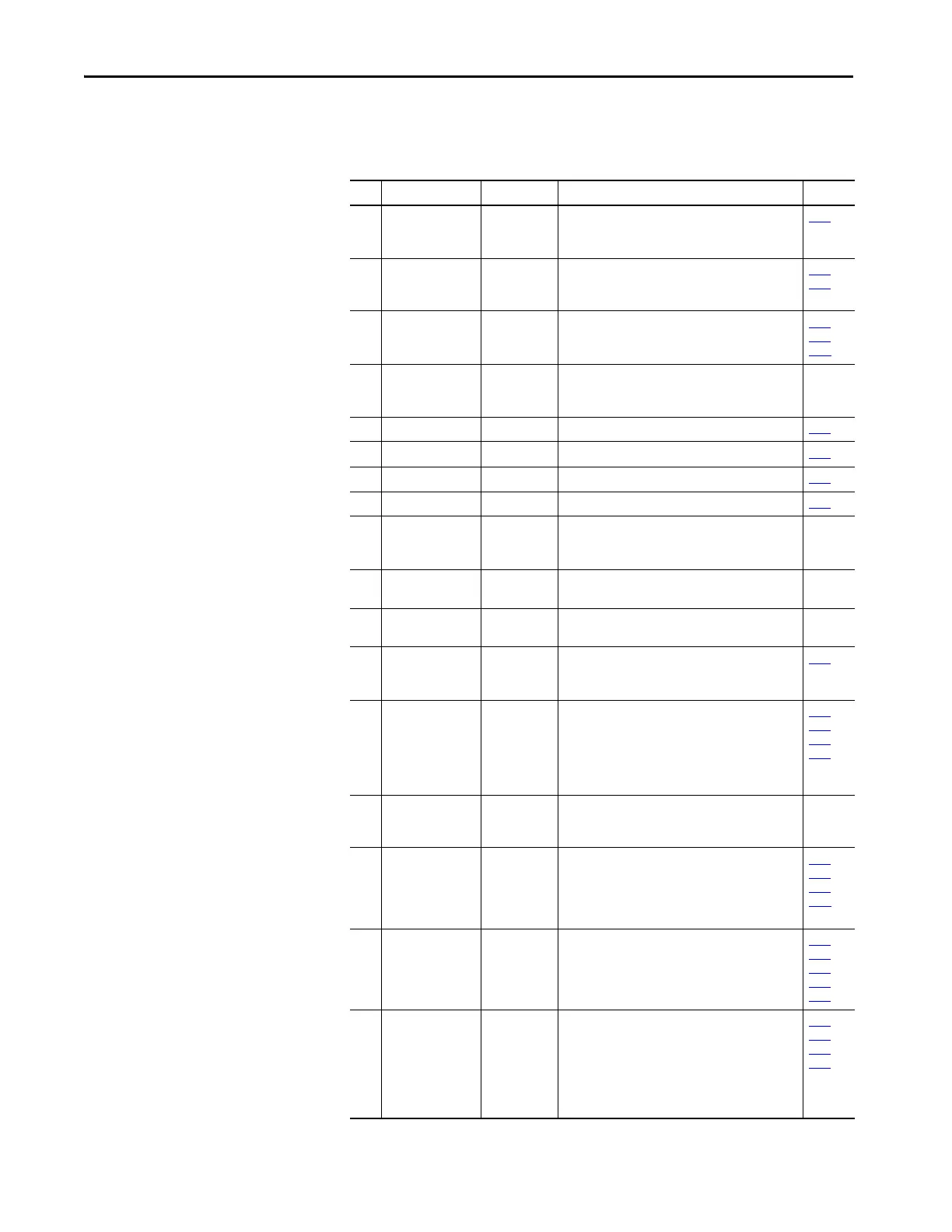
Table 9 - Control I/O Terminal Designations
No. Signal Default Description Param.
01 Stop
(1)
/
Function Loss
Coast Factory installed jumper or a normally closed input
must be present for the drive to start.
Program with P036 [Start Source].
P036
(1)
02 Start/Run FWD – HAND Mode: Command comes from Integral Keypad.
AUTO Mode: I/O Terminal 02 is active.
Program with P036 [Start Source].
P036,
P037
03 Direction/Run REV Rev Disabled To enable reverse operation, program with A166
[Reverse Disable].
Program with P036 [Start Source].
P036,
P037,
A166
04 Digital Common – For digital inputs. Tied to I/O Terminal 09.
Electronically isolated with digital inputs from analog
I/O and opto output.
05 Digital Input 1 Purge
(2)
Program with T051 [Digital In1 Sel]. T051
06 Digital Input 2 Local Program with T052 [Digital In2 Sel]. T052
07 Digital Input 3 Clear Fault Program with T053 [Digital In3 Sel]. T053
08 Digital Input 4 Comm Port Program with T054 [Digital In4 Sel]. T054
09 Digital Common – For digital inputs. Tied to I/O Terminal 04.
Electronically isolated with digital inputs from analog
I/O and opto output.
10 Opto Common – For opto-coupled outputs. Electronically isolated with
opto output from analog I/O and digital inputs.
11 +24V DC – Drive supplied power for digital inputs.
Referenced to Digital Common. Max. Output: 100mA.
12 +10V DC – Drive supplied power for 0-10V external
potentiometer.
Referenced to Analog Common. Max. Output: 15mA.
P038
13 Analog Input 1 0-10V External 0-10V (unipolar), 0-20mA or 4-20mA input
supply or potentiometer wiper. Default input is 0-10V.
For current (mA) input, set AI1 DIP Switch to 20mA.
Program with T069 [Analog In 1 Sel].
Input Impedance: 100k ohm (Voltage Mode)
250 ohm (Current Mode)
T069,
T070,
T071,
T072
14 Analog Common 1 – Common for Analog Input 1 and Analog Output 1 and
2. Electrically isolated from digital I/O and opto
output.
15 Analog Output 1 OutFreq 0-10 Default analog output is 0-10V.
For current (mA) value, set AO1 DIP Switch to 20mA.
Program with T082 [Analog Out1 Sel].
Maximum Load: 4-20mA = 525 ohm (10.5V)
0-10V = 1k ohm (10mA)
P038
,
T051...
T054,
A152
16 Analog Output 2 OutCurr 0-10 Default analog output is 0-10V.
For a current (mA) value, set AO2 DIP Switch to 20mA.
Program with T085 [Analog Out2 Sel].
Maximum Load: 4-20mA = 525 ohm (10.5V)
0-10V = 1k ohm (10mA)
T082,
T084,
T085,
T086,
T087
17 Analog Input 2 0-10V Optically isolated external 0-10V (unipolar), ±10V
(bipolar), 0-20mA or 4-20mA input supply or
potentiometer wiper. Default input is 0-10V.
For current (mA) input, set AI2 DIP Switch to 20mA.
Program with T073 [Analog In 2 Sel].
Input Impedance: 100k ohm (Voltage Mode)
250 ohm (Current Mode)
T073,
T074,
T075,
T076
 Loading...