1756-6.5.3 - December 1999
10-18 Controlling I/O Over a ControlNet Network
Test the Example Application
You will test the example application by using a momentary switch to
simulate a parts sensor.
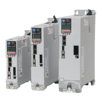
1. Wire the 1756-IB16 digital input module as shown in the following
figure:
2. Restore the RSLogix5000 software and place the controller in Run
mode.
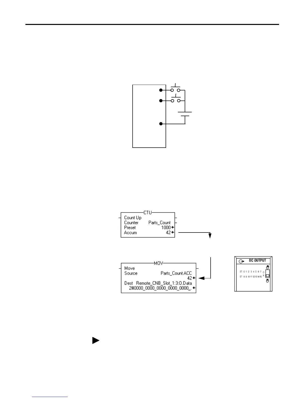
3. Repeatedly press and release the momentary switch at IN-0 on the
1756-IB16 digital input module. Each time you press the switch you
should see the Parts_Count accumulated value increment on the screen
and the LED display of the OB16I output module increment in binary.
4. Press and release the momentary switch at IN-1 on the 1756-IB16 digital
input module. You should see the accumulated value of the Parts_Count
reset to zero and all of the LEDs on the 1756-OB16I output module turn
off.
This completes the scheduled I/O example.
IN-0
IN-2
GND-0
1
3
9
+
–
1756-IB16
24V
Accumulated Value
will increment and
be moved to Output
module.
LED display will
increment in
binary count
Refer to the ControlLogix Digital I/O Modules User Manual, publication
1756-6.5.8, for assistance in wiring and debugging the I/O modules.
 Loading...


