Process Control Instructions
206 Rockwell Automation Publication 1756-RM006K-EN-P - November 2018
Structure
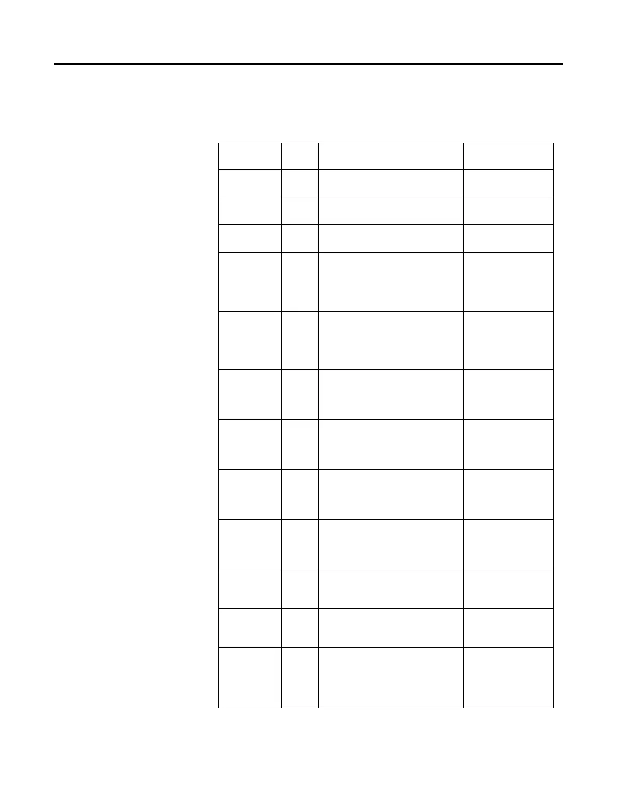
The following table describes the input parameters in the MMC function block.
Input Parameters Data
Type
Description Values
EnableIn BOOL Enable Input. If False, the function block will not
execute and outputs are not updated.
Default=TRUE
PV1 REAL Scaled process variable input 1. This value is
typically read from an analog input module.
Valid = any float
Default = 0.0
PV2 REAL Scaled process variable input 2. This value is
typically read from an analog input module.
Valid = any float
Default = 0.0
PV1Fault BOOL PV1 bad health indicator. If PV1 is read from an
analog input, then PV1Fault will normally be
controlled by the analog input fault status. If
PVFault is TRUE, it indicates an error on the input
module, set bit in Status.FALSE = Good Health
Default = FALSE
PV2Fault BOOL PV2 bad health indicator. If PV2 is read from an
analog input, then PV2Fault will normally be
controlled by the analog input fault status. If
PVFault is TRUE, it indicates an error on the input
module, set bit in Status.FALSE = Good Health
Default = FALSE
PV1EUMax REAL Maximum scaled value for PV1. The value of PV1
and SP1 that corresponds to 100% span of the
Process Variable. If PV1EUMax ≤ PV1EUMin, set
bit in Status.
Valid = PV1EUMin <
PV1EUMax <= maximum
positive float
Default = 100.0
PV2EUMax REAL Maximum scaled value for PV2. The value of PV2
and SP2 that corresponds to 100% span of the
Process Variable. If PV2EUMax ≤ PV2EUMin, set
bit in Status.
Valid = PV2EUMin <
PV2EUMax <= maximum
positive float
Default = 100.0
PV1UEMin REAL Minimum scaled value for PV1. The value of PV1
and SP1 that corresponds to 0% span of the
Process Variable. If PV1EUMax ≤ PV1EUMin, set
bit in Status.
Valid = maximum negative
float <= PV1EUMin <
PV1EUMax
Default = 0.0
PV2UEMin REAL Minimum scaled value for PV2. The value of PV2
and SP2 that corresponds to 0% span of the
Process Variable. If PV1EUMax ≤ PV1EUMin, set
bit in Status.
Valid = maximum negative
float <= PV2EUMin <
PV2EUMax
Default = 0.0
SP1Prog REAL SP1 Program value, scaled in PV units. SP1 is set
to this value when Program control.
Valid = SP1LLimit to
SP1HLimit
Default = 0.0
SP2Prog REAL SP2 Program value, scaled in PV units. SP2 is set
to this value when Program control.
Valid = SP2LLimit to
SP2HLimit
Default = 0.0
SP1Oper REAL SP1 Operator value, scaled in PV units. SP1 set to
this value when Operator control.
If value of SP1Prog or SP1Oper < SP1LLimit or >
SP1HLimit, set bit in Status and limit value used
for SP.
Valid = SP1LLimit to
SP1HLimit
Default = 0.0
 Loading...