404 Rockwell Automation Publication 1756-RM006K-EN-P - November 2018
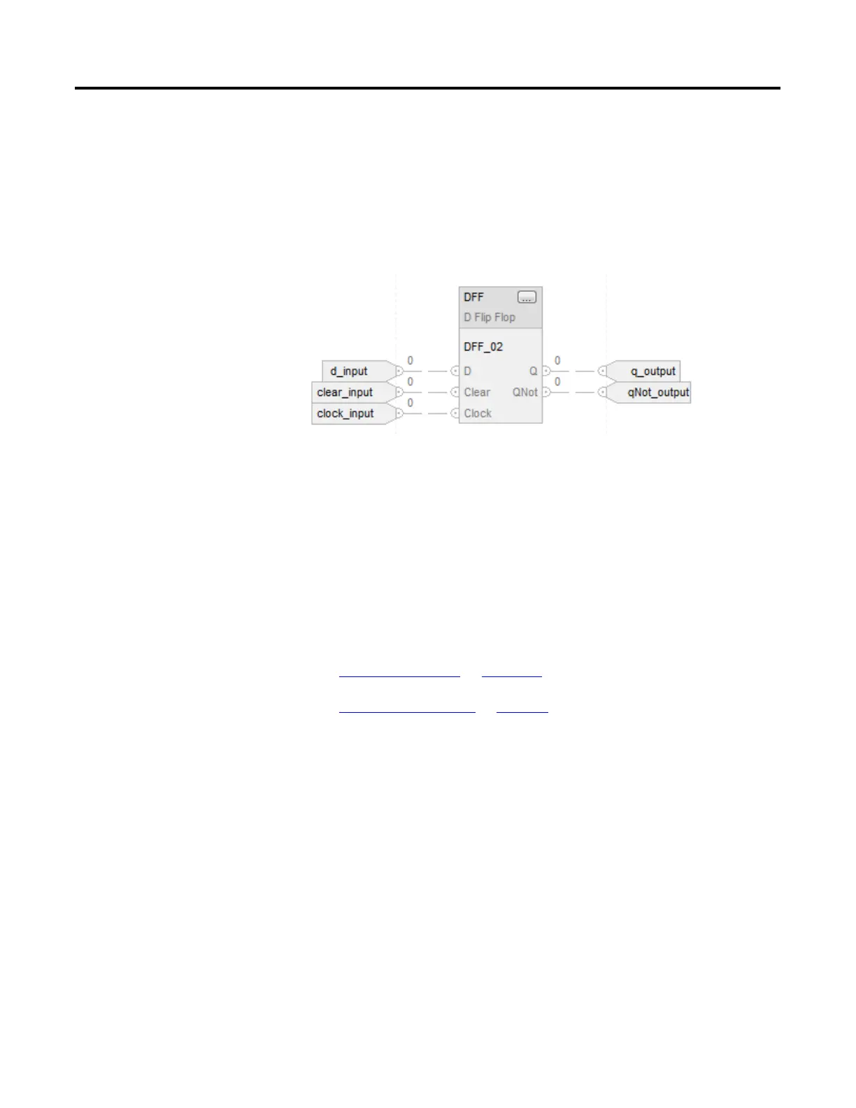
Example
When Clock goes from cleared to set, the DFF instruction sets Q = D. When
Clear is set, Q is cleared. The DFF instruction sets QNot to the opposite state of
Q.
Function Block
Structu
red Text
DFF_03.D := d_input;
DFF_03.Clear := clear_input;
DFF_03.Clock := clock_input;
DFF(DFF_03);
q_output := DFF_03.Q;
qNot_output := DFF_03.QNot;
See also
Common Attributes on page 537
Structured Text Syntax on page 508
This information applies to the CompactLogix 5370, ControlLogix 5570,
Compact GuardLogix 5370, GuardLogix 5570, Compact GuardLogix 5380,
CompactLogix 5380, CompactLogix 5480, ControlLogix 5580, and GuardLogix
5580 controllers.
The JKFF instruction complements the Q and QNot outputs when the Clock
input transitions from cleared to set.
Available Languages
Ladder Diagram
This instruction is not available in ladder diagram logic.
 Loading...