Process Control Instructions
246 Rockwell Automation Publication 1756-RM006K-EN-P - November 2018
See also
MMC Function Block Tuning Procedure on page 247
MMC Function Block Tuning Errors on page 246
The following example describes using an MMC function block to control a
splitter. Refer to the MMC Function Block Splitter Example Configuration in
Module Multivariable Control ( MMC).
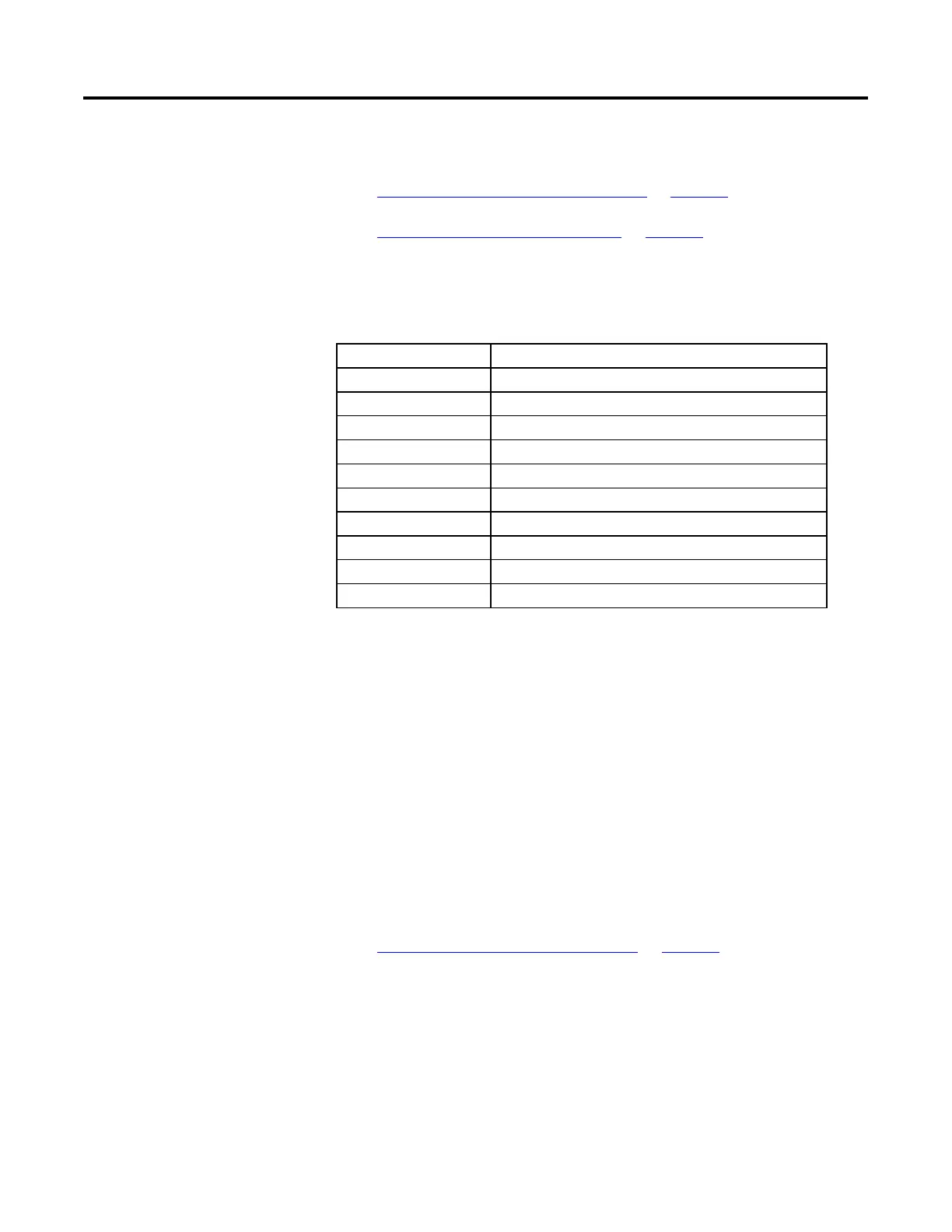
Item Description
PV1 Top composition (more important)
PV2 Bottom composition (less important)
Active 1st CV for PV1 CV1 (reflux ratio)
Active 2nd CV for PV1 CV3 (pressure setpoint)
Active 3rd CV for PV1 CV2 (steam (flow)
Active 1st CV for PV2 CV2
Active 2nd CV for PV2 CV3
Active 3rd CV for PV2 CV1
TargetCV CV3 (pressure should be held constant if possible)
CV3Target 60% (of pressure range)
The MMC calculates CV1, CV2, and CV3 so that the control goals are
accomplished in the following order of importance:
1. Control PV1 to SP1 (PV1 is always considered more important than PV2)
2. Control PV2 to SP2
3. Control CV3 to its target value
CV1 is selected as the most active control for PV1 and CV2 as the most active for
PV2. If either CV1 or CV2 saturates or is put in Manual mode, the control
variable will use CV3 to maintain PV1 and PV2 at the setpoints.
See also
Module Multivariable Control ( MMC) on page 204
If an error occurs during the tuning procedure, the tuning is aborted, and an
appropriate AtuneStatus bit is set. Also, a user can abort the tuning by setting the
AtuneAbort parameter.
After an abort, the CV assumes its value before the step change, and the
GainTuned, TCTuned, DTTuned, and RespTCTuned parameters are not
updated. The AtuneStatus parameter identifies the reason for the abort.
Block for Splitter Control
MMC Function Block Tuning
Errors
 Loading...