Equipment Phase Instructions
446 Rockwell Automation Publication 1756-RM006K-EN-P - November 2018
To take action
when a failure
occurs, monitor
the Failure
member of the
PHASE tag.
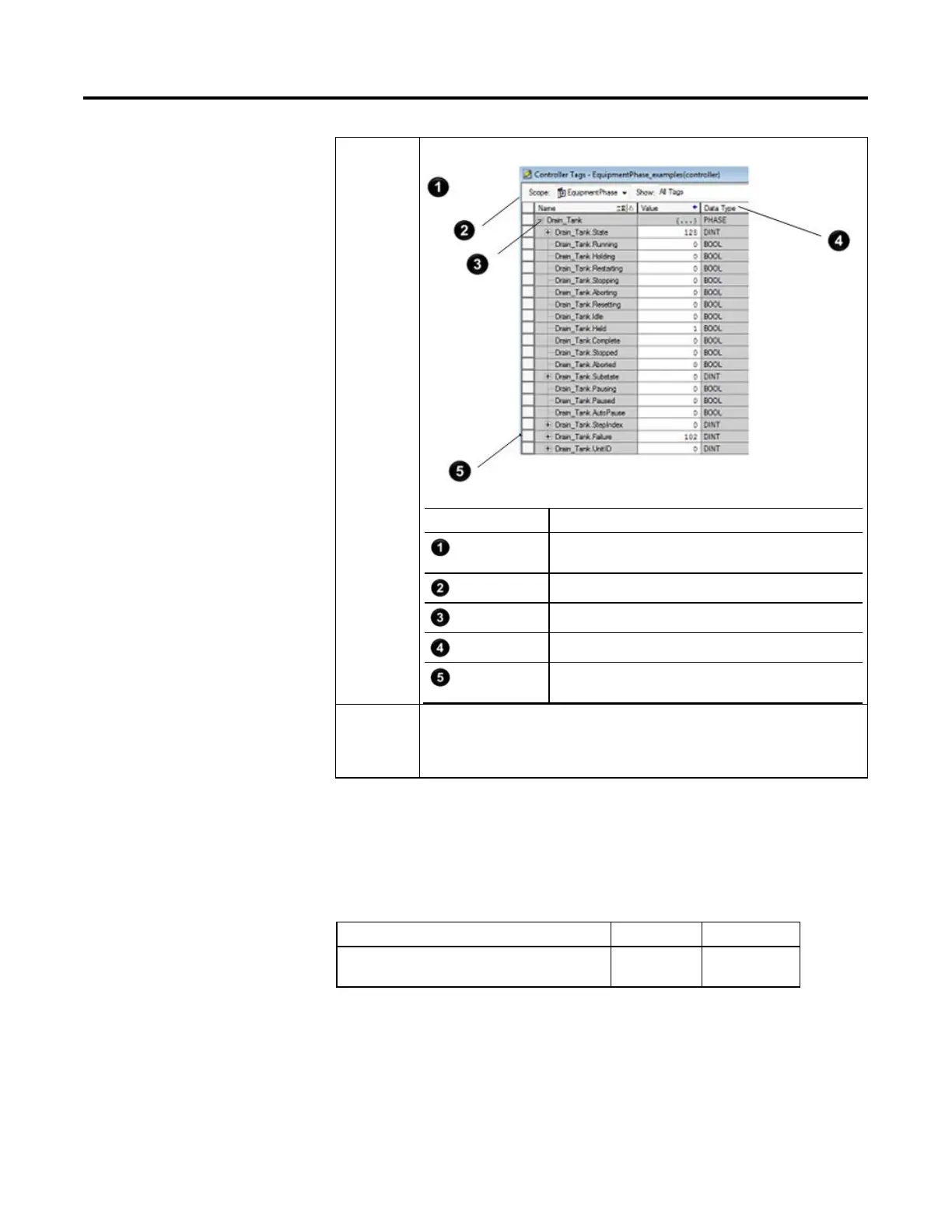
The PFL instruction writes its value to the Failure member of the PHASE tag for the equipment phase.
Number Description
When creating an equipment phase, the Logix Designer application
creates a tag for the status of the equipment phase.
controller scope
Name = phase_name
PHASE data type
The PFL instruction writes its value to the failure member for the
equipment phase.
To clear the
failure code, use
a PCLF
instruction.
Use a PCLF instruction to clear the failure code of an equipment phase. Instructions such as a CLR or
MOV will not change the failure code.
Affects Math Status Flags
No.
Major/Minor Faults
A major fault will occur if: Fault type Fault code
Instruction is called from outside an Equipment Phase
program.
4 91
See Index Through Arrays below for array-index faults.
 Loading...