Timer and Counter Instructions
Chapter 5
56
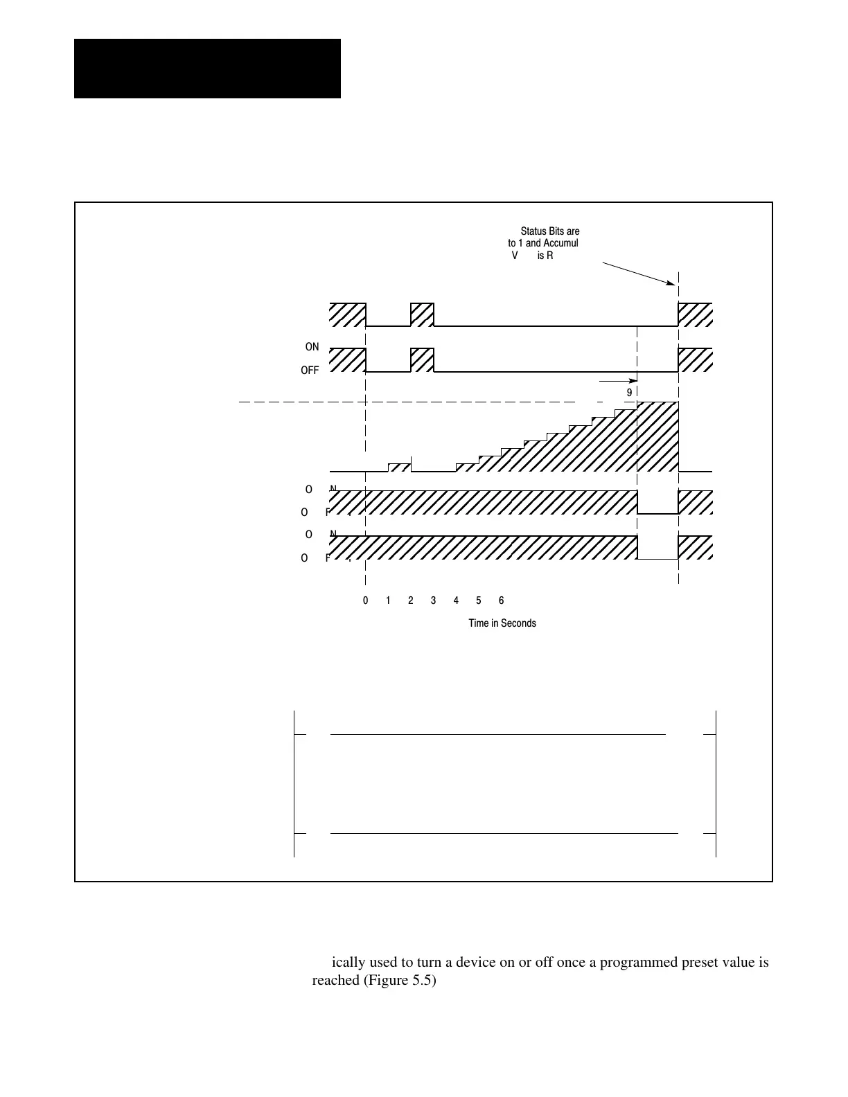
Figure 5.4
Timer
OffDelay
, Timing Diagram for a Preset Value of 9 Seconds
ON
OFF
ON
OFF
0123456789101112
ÉÉÉÉÉÉÉÉÉÉÉ
ÉÉÉÉÉÉÉÉÉÉÉ
ÉÉÉÉÉÉÉÉÉÉÉ
ÉÉÉÉÉÉÉÉÉÉÉ
ÉÉÉÉÉÉÉÉÉÉÉ
1
2
0
1
2
0
4
5
6
3
7
8
9
ON
OFF
ON
OFF
Time
in Seconds
Status Bits are
to 1 and Accumul
V
alue is Reset Wh
Input Switch is C
Input Switch 1
13/05
Enable Bit 047/17
Preset V
alue
Accumulated V
alue
T
imed Bit 047/15
Output Lamp 01
1/04
Rung 1 - T
OF Instruction
Preset for 9 Sec. Delay
Rung 2 - T
imer Turns Off
Bit 01
1/04 When T
imed Out
||
05
( TOF )
1.0
113 047
||
15
()
04
047 011
PR 009
AC 009
Input Switch
T
imed Bit
T
imer OnDelay
Output Lamp
AC = PR
ÉÉÉÉÉÉÉÉÉÉÉÉÉÉÉ
ÉÉÉÉÉÉÉÉÉÉÉÉÉÉÉ
ÉÉÉÉÉÉÉÉÉÉÉÉÉÉÉ
ÉÉÉÉÉÉÉÉÉÉÉÉÉÉÉ
The Retentive Timer instruction (RTO), much like the TON instruction, is
typically used to turn a device on or off once a programmed preset value is
reached (Figure 5.5).
5.1.3
Retentive Timer Instruction
Artisan Technology Group - Quality Instrumentation ... Guaranteed | (888) 88-SOURCE | www.artisantg.com
 Loading...


