Introduction to Programming
Chapter 4
42
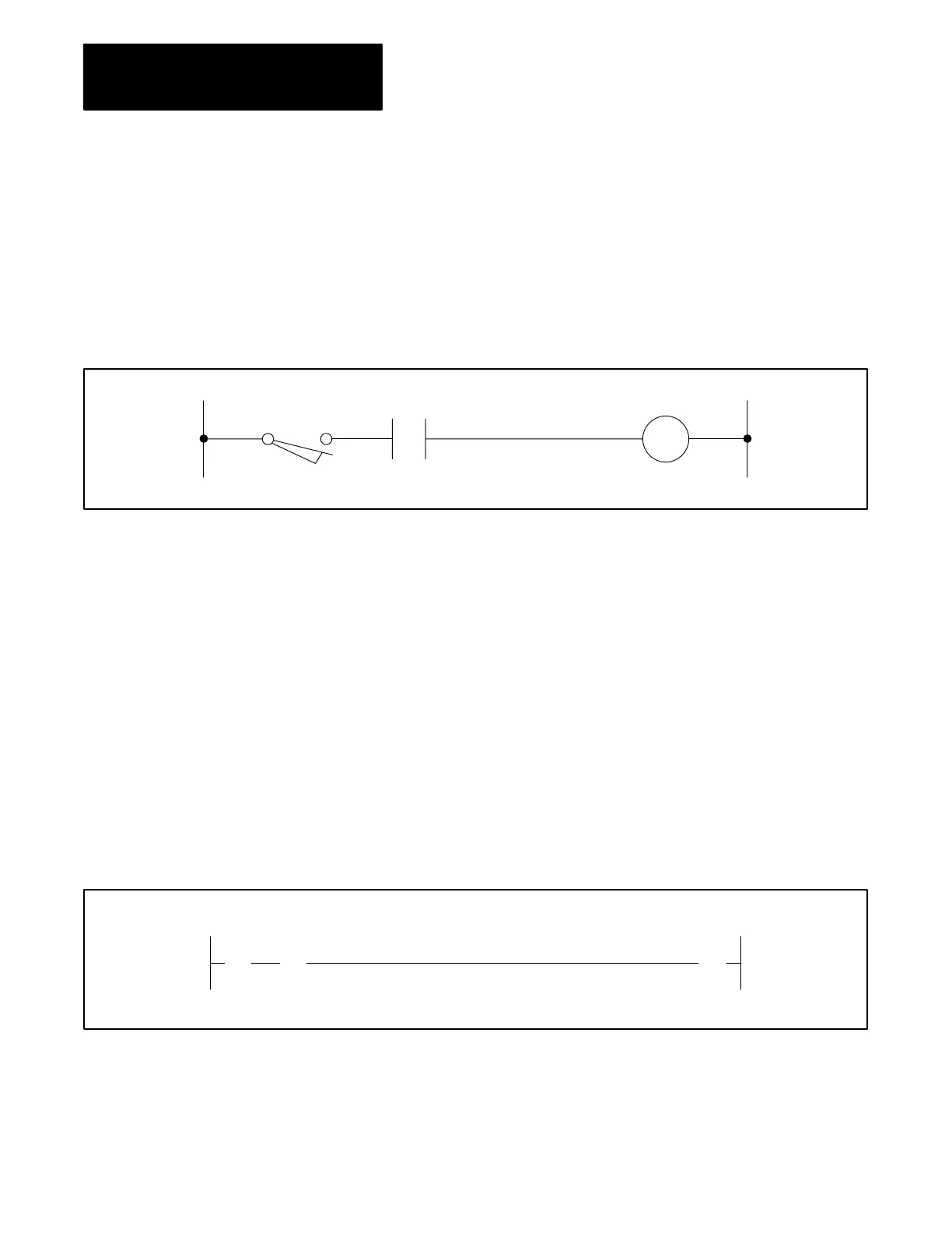
Programmable controller ladder diagram logic closely resembles hardwired
relay logic. Hardwired relay control systems require electrical continuity
to turn output devices on and off. For example, the relay diagram in
Figure 4.1 shows that limit switch LS1 and relay contact CR2 must be
closed to energize relay coil CR4.
Figure 4.1
Relay
Diagram
LS1
CR2
CR4
Similarly, in each rung of ladder diagram program, logic continuity is
needed to energize or de-energize the output instructions, and ultimately,
the output device. For example, the ladder diagram rung in Figure 4.2
shows the two input devices and the output device that are assigned bit
addresses in the data table. The bit addresses correspond to the location of
the I/O devices wired to the I/O modules. When the two input instructions
are logically true, or the bits in memory are on, logic continuity is
established. This causes the output instruction to be true and the output
device to be turned on.
The bit address of an instruction is defined by a word address and a bit
number in the data table. The word address is written above the instruction
and the bit number below it.
Figure 4.2
Ladder
Diagram Rung
LS1
113
||
02
CR2
113
03
CR4
012
()
16
||
4.2
Ladder Diagram Logic
Artisan Technology Group - Quality Instrumentation ... Guaranteed | (888) 88-SOURCE | www.artisantg.com
 Loading...


