Data Table
Chapter 3
322
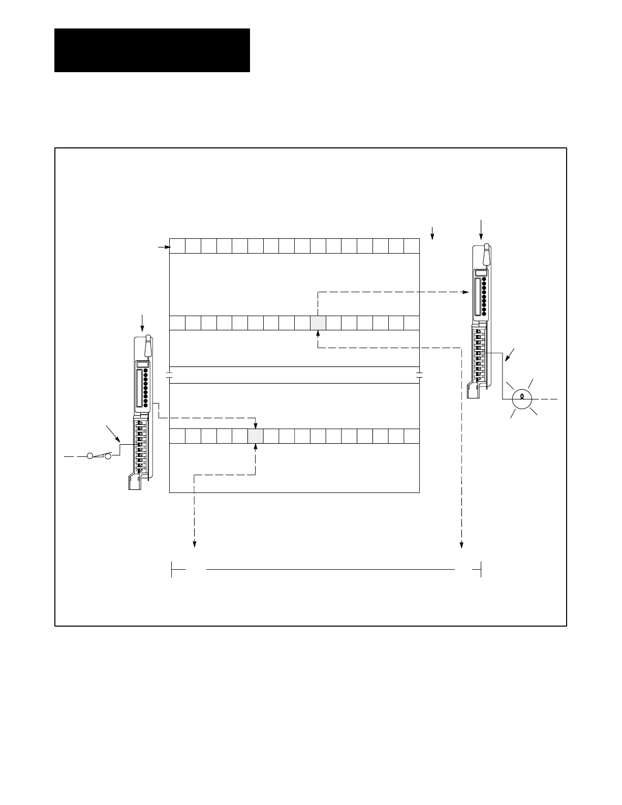
Figure 3.7
Relationship
of Word Address to Hardware
17 16 15 14 13 12 11 10 07 06 05 04 03 02 01 00
100101
1
11110
0
00100
012
8
10001011110000
3Digit
Word Addresses
Output Module in
Assigned I/O Rack No. 1,
I/O Group No. 2
Output T
erminal
012/06
010
8
Energized
Output
Input Image T
able
BIT 113/12
1 = ON
0 = OFF
UserProgrammed Rung
Input T
erminal
113/12
Input Module in
I/O Rack No. 1,
I/O Group No. 3
2-Digit Bit and
T
erminal Address
Output Image T
able
BIT 012/06
1 = ON
0 = OFF
012
( )| |
Closed
Input
017
8
113
8
110
8
177
8
0612
113
Instruction
Intensified
When Enabled
When the input device wired to terminal 113/12 opens, the input module
senses no voltage. The Off condition is reflected in the input image table
bit 113/12. During the program scan, the processor examines bit 113/12
for an On (1) condition. Since the bit is off (0), logic continuity is not
established, the rung is false and the output instruction is not intensified.
The processor then sets output image table bit 012/06 to off (0). In the next
I/O scan, it turns off terminal 012/06 and the output device wired to this
terminal is turned off.
Artisan Technology Group - Quality Instrumentation ... Guaranteed | (888) 88-SOURCE | www.artisantg.com
 Loading...


