Block Transfer
Chapter 10
107
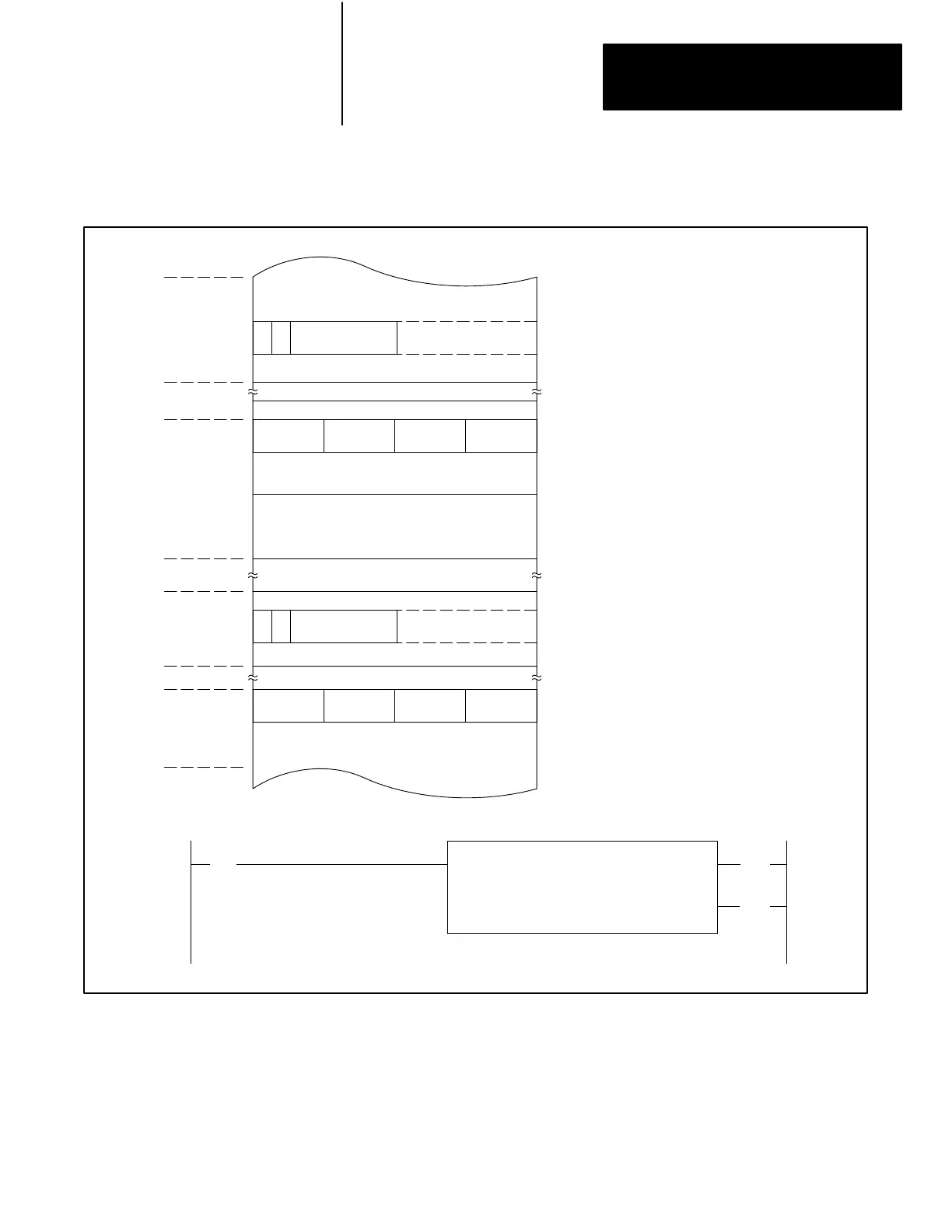
Figure 10.4
Data
T
able Locations for a Block T
ransfer Read Instruction
Data Table
Block T
ransfer Data
Block Length
Code
R
1
R
1
121
060
Output
Image
Table
Timer/
Counter
Accumulated
Area
Input
Image
Table
Timer/
Counter
Preset
Area
010
012
017
027
030
060
067
110
112
117
130
Output image table byte
contains read enable bit
and block length in
binary code.
Data address contains
module address in BCD.
First File Word
Last File Word
Input image table byte
contains done bit.
Storage location of file
address contains file
address in BCD.
R = Bit 17 = Read
BLOCK XFER READ
DAT
A ADDR:
030
MODULE ADDR:
121
BLOCK LENGTH:
08
FILE: 060067
012
(EN)
17
112
(DN)
17
113
||
02
The module is located in rack 1, module group 2, slot 1. Therefore, the
control and status bytes corresponding to the module’s address in the
output and input image tables are at word address 012 and 112 (upper
bytes) respectively. The address of the read bit and done bit for the
instruction are 012/17 and 112/17, respectively.
Artisan Technology Group - Quality Instrumentation ... Guaranteed | (888) 88-SOURCE | www.artisantg.com
 Loading...


