Shift Register Instructions
Chapter 13
134
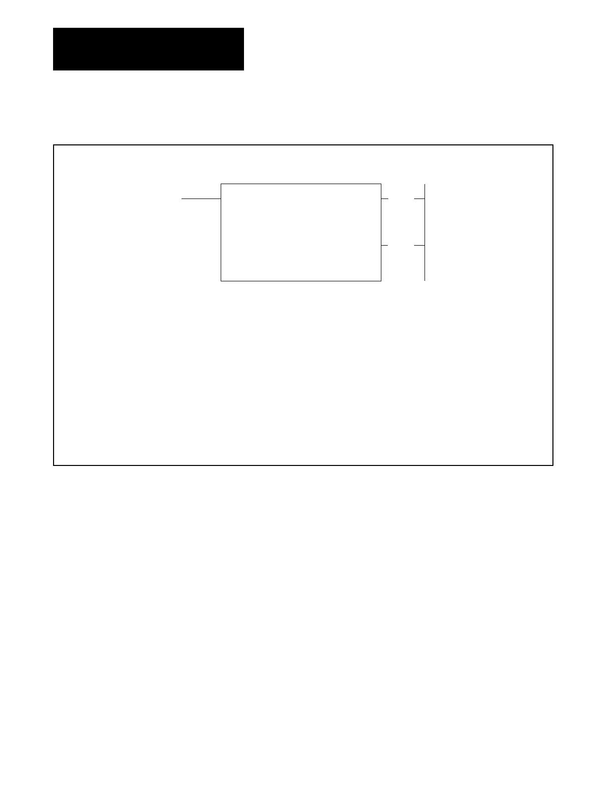
Figure 13.3
SHIFT
FILE UP Format
SHIFT FILE UP
COUNTER ADDR:
030
FILE LENGTH: 001
FILE: 110-110
INPUT ADDR:
010
OUTPUT ADDR: 010
RA
TE PER SCAN:
001
030
(EN)
17
Numbers
shown are default values. Bold numbers must be replaced by userentered values. The number of default address digits
initially displayed 3, 4, or 5 will depend on the size of the data table. Initially displayed default values are governed by the I/O rack
configuration.
COUNTER ADDRESS
:
Address of the instruction in the accumulated value area of the data table.
FILE LENGTH :
Number of words in file (preset value of the counter).
FILE :
Starting word of file.
INPUT ADDRESS
:
Address of input word.
OUTPUT ADDRESS
:
Address of output word.
RA
TE PER SCAN
:
Number of words operated upon per scan.
030
(DN)
15
Figure 13.4 shows the format of Figure 13.3 after the following conditions
have been entered.
COUNTER ADDR – 200
FILE LENGTH – 064
FILE – File starts and ends at words 400 and 477 respectively
INPUT ADDR – 120
OUTPUT ADDR – 500
RATE PER SCAN – 064
This is the complete mode. A word is shifted into and a word is shifted out
of the file each scan.
The procedure for using the data monitor mode for data entry or monitor is
presented in Chapter 12.
Artisan Technology Group - Quality Instrumentation ... Guaranteed | (888) 88-SOURCE | www.artisantg.com
 Loading...


