Rockwell Automation Publication 20A-UM001N-EN-P - July 2013 113
Application Notes Appendix C
Motor Overload
For single motor applications the drive can be programmed to protect the motor
from overload conditions. An electronic thermal overload I
2
T function emulates
a thermal overload relay. This operation is based on these three parameters:
• 042 [Motor NP FLA]
• 047 [Motor OL Hertz]
• 048 [Motor OL Factor]
[Motor NP FLA] is multiplied by [Motor OL Factor] to let you define the
continuous level of current allowed by the motor thermal overload.
[Motor OL Hertz] is used to adjust the frequency below where the motor
overload is derated.
The motor can operate up to 102% of FLA continuously. If the drive had just
been activated, it runs at 150% of FLA for 180 seconds. If the motor had been
operating at 100% for over 30 minutes, the drive runs at 150% of FLA for 60
seconds. These values assume the drive is operating above [Motor OL Hertz],
and that [Motor OL Factor] is set to 1.00.
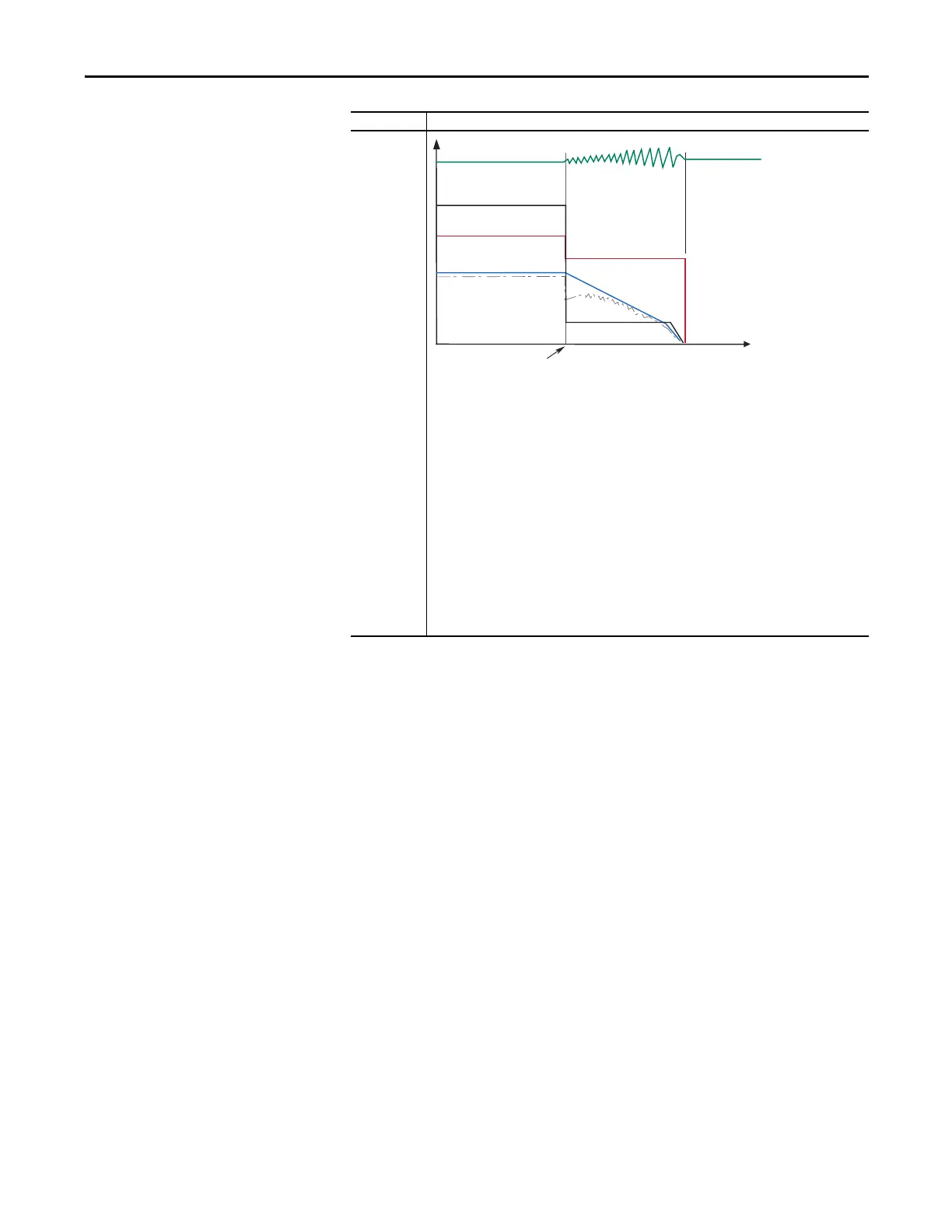
Fast Brake
This method takes advantage of the characteristic of the induction motor whereby frequencies greater
than zero (DC braking) can be applied to a spinning motor that provides more braking torque without
causing the drive to regenerate.
1. On Stop, the drive output decreases based on the motor speed, keeping the motor out of the regen
region. This is accomplished by lowering the output frequency below the motor speed where
regeneration does not occur. This causes excess energy to be lost in the motor.
2. The method uses a PI based bus regulator to regulate the bus voltage to a reference (for example
750V) by automatically decreasing output frequency at the proper rate.
3. When the frequency is decreased to a point where the motor no longer causes the bus voltage to
increase, the frequency is forced to zero. DC brake is used to complete the stop if the DC Braking
Time is non-zero, then the output is shut off.
4. Use of the current regulator ensures that over current trips don’t occur and enable an easily
adjustable and controllable level of braking torque.
5. Use of the bus voltage regulator results in a smooth, continuous control of the frequency and forces
the maximum allowable braking torque to be utilized at all times.
6. Important: For this feature to function properly the active Bus Reg Mode A or B must be set to
Adjust “Freq” and NOT be “Disabled”.
Mode Description
Stop
Command
Time
Output Voltage
Output Current
Motor Speed
Bus Voltage
Command Speed

 Loading...


