14 Rockwell Automation Publication 20A-UM001N-EN-P - July 2013
Chapter 1 Programming and Parameters
How Parameters are
Organized
LED HIM (human interface module)
The LED HIM displays parameters in numbered list order. Parameters are
accessed by first selecting the file letter, then a parameter number.
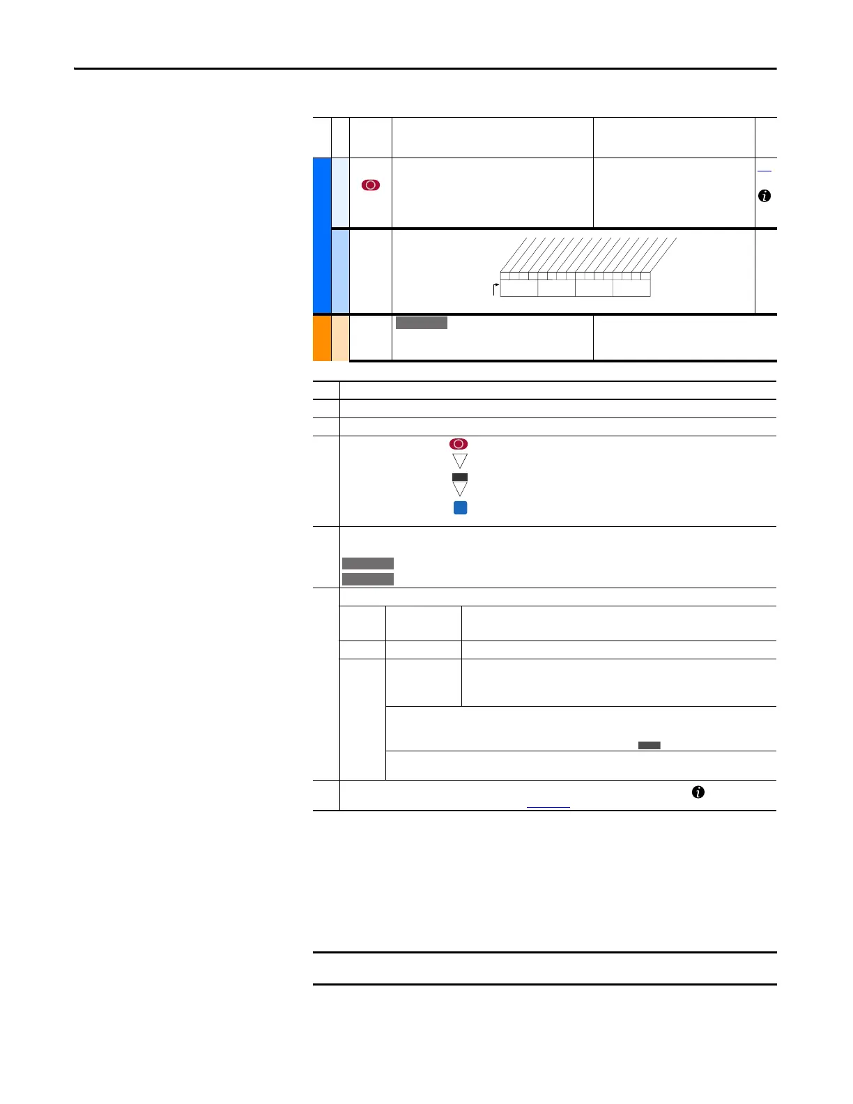
No. Description
➊ File – Lists the major parameter file category.
➋ Group – Lists the parameter group within a file.
➌
No. – Parameter number = Parameter value cannot be changed until drive is stopped.
= 32 bit parameter.
= 32 bit parameter (only in Enhanced Control drive).
= Parameter that is displayed when [Motor Cntl Sel] is set to “4.”
➍ Parameter Name and Description – Parameter name as it appears on an LCD HIM, with a brief description of
the parameters function.
= This parameter is specific to Standard Control drives.
= This parameter is only available with Enhanced Control drives.
➎ Values – Defines the various operating characteristics of the parameter. Three types exist.
ENUM
Default:
Options:
Lists the value assigned at the factory. “Read Only” = no default.
Displays the programming selections available.
Bit Bit #: Lists the bit place holder and definition for each bit.
Numeric
Default:
Min/Max:
Units:
Lists the value assigned at the factory. “Read Only” = no default.
The range (lowest and highest setting) possible for the parameter.
Unit of measure and resolution as shown on the LCD HIM.
Important: Some parameters have two unit values:
· Analog inputs can be set for current or voltage with 320 [Anlg In Config].
· Values that pertain only to Enhanced Control drives are indicated by “
.”
Important: When sending values through DPI ports, simply remove the decimal point to arrive at the correct
value (for example, to send “5.00 Hz,” use “500”).
➏ Related – Lists parameters (if any) that interact with the selected parameter. The symbol “ ” indicates that
additional parameter information is available in Appendix C.
File
Group
No.
Parameter Name and Description Values
Related
UTILITY (file E)
Drive . . .
198 [Load Frm Usr Set]
Loads a previously saved set of parameter values
from a selected user set location in drive
nonvolatile memory to active drive memory.
Default:
Options:
0
0
1
2
3
“Ready”
“Ready”
“User Set 1”
“User Set 2”
“User Set 3”
199
Diagnostics
216 [Dig In Status]
Status of the digital
inputs.
MOTOR . . .
Torq . . .
059 [SV Boost Filter]
Sets the amount of filtering used to boost voltage
during Sensorless Vector operation.
Default:
Min/Max:
Units:
500
0/32767
1
000000xx000000xx
10 01234567891112131415
1=Input Present
0=Input Not Present
x =Reserved
Bit #
Digital In1
Digital In2
Digital In3
Digital In4
Digital In5
Digital In6
In1 DLogRslt
(1)
In2 DLogRslt
(1)
In3 DLogRslt
(1)
In4 DLogRslt
(1)
In5 DLogRslt
(1)
In6 DLogRslt
(1)
Nibble 1Nibble 2Nibble 3Nibble 4
(1)
Enhanced firmware 2.001 & later.
E C
E C
The PowerFlex 70 Enhanced Control drive does not support the LED HIM.

 Loading...


