116 Rockwell Automation Publication 20A-UM001N-EN-P - July 2013
Appendix C Application Notes
The actual output frequency at maximum speed reference is the sum of the speed
reference plus speed adder components from functions such as slip
compensation.
The Overspeed Limit is entered in Hertz and added to Maximum Speed and the
sum of the two (Speed Limit) limit the output frequency. This sum (Speed
Limit) must is compared to Maximum Frequency and an alarm is initiated that
prevents operation if the Speed Limit exceeds Maximum Frequency.
Speed Reference Control
“Auto” Speed Sources
The drive speed command can be obtained from a number of different sources.
The source is determined by drive programming and the condition of the speed
select digital inputs, Auto/Manual digital input or reference select bits of a
command word.
The default source for a command reference (all speed select inputs open or not
programmed) is the selection programmed in P90 [Speed Ref A Sel]. If any of the
speed select inputs are closed, the drive uses other parameters as the speed
command source.
If a communication device is the source of the speed reference, refer to the
appropriate communications manual for additional information.
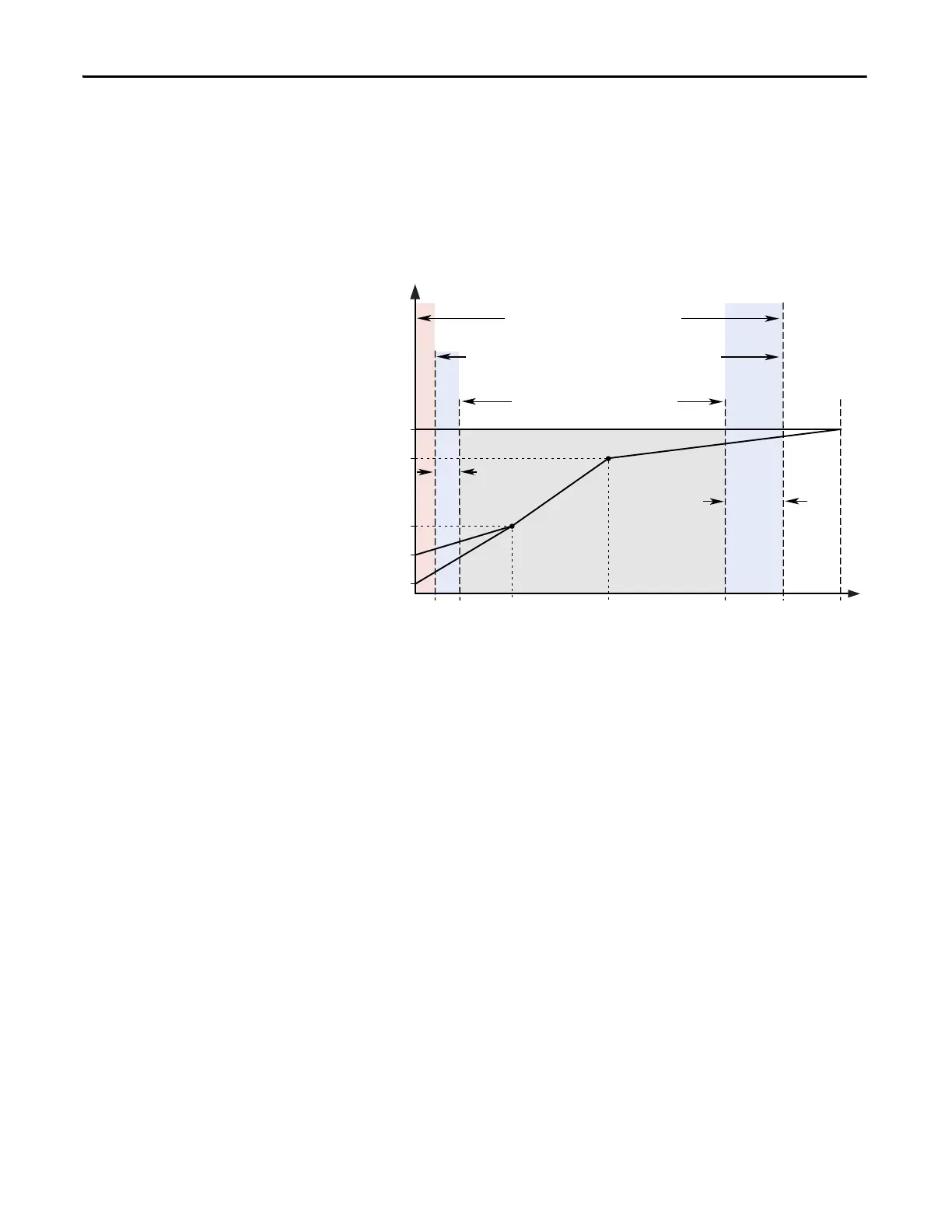
Frequency
Output Voltage
Note 1: The lower limit on this range can be 0 depending on the value of Speed Adder
Overspeed
Limit
Frequency Trim
due to Speed
Control Mode
Maximum
Voltage
Motor NP
Voltage
Run
Boost
Break
Voltage
Start
Boost
Allowable Output Frequency Range - Normal Operation
1
Allowable Speed Reference Range
Allowable Output Frequency Range -
Bus Regulation or Current Limit
Maximum
Frequency
Motor NP Hz0 Break
Frequency
Maximum
Speed
Minimum
Speed
Output
Frequency
Limit

 Loading...


