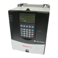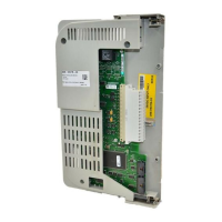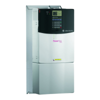

Do you have a question about the Allen-Bradley PowerFlex and is the answer not in the manual?
| Category | DC Drives |
|---|---|
| Manufacturer | Allen-Bradley |
| Series | PowerFlex |
| Communication Options | EtherNet/IP, DeviceNet, ControlNet |
| Protection Features | Overcurrent, Overvoltage, Undervoltage, Overtemperature, Short Circuit |
| Enclosure Type | NEMA 1, NEMA 12, NEMA 4/4X |
| Operating Temperature | 0°C to 40°C (32°F to 104°F) |
| Storage Temperature | -40°C to 70°C (-40°F to 158°F) |
| Humidity | 5% to 95% (non-condensing) |
| Altitude | Up to 1000m (3280 ft) without derating |
Details specifications for PowerFlex 70 and 700 drives, including protection and certification.
Lists input/output ratings, environmental conditions, and electrical specifications for the drives.
Provides guidelines for derating based on ambient temperature and load conditions.
Covers altitude derating factors and typical efficiency charts for PowerFlex 70 drives.
Presents diagrams and tables for PowerFlex 70 frame dimensions and ratings.
Diagrams showing bottom view dimensions for PowerFlex 70 Frames A and B.
Details overall dimensions, knockout, and cutout dimensions for flange mounting.
Presents diagrams and tables for PowerFlex 700 frame dimensions and ratings.
Sets the rate at which the drive ramps up its output frequency.
Details suitability for circuits up to 200,000 rms symmetrical amperes, 600V.
Indicates situations affecting drive operation, classified as Type 1 or Type 2 alarms.
Describes controlling a process with a 4-20 mA analog signal as speed reference.
Lists purposes for analog inputs: speed ref, trim, PI loop, limits.
Describes analog outputs used for annunciating drive conditions and values.
Allows overriding selected reference with HIM button or digital input.
Automatically performs fault reset and start attempts without user intervention.
Manages DC bus voltage by adjusting output frequency to counter regeneration.
Explains bus voltage regulator selection and set points in PowerFlex 70 and 700.
Discusses limitations due to Reflected Wave and Cable Charging.
Discusses acceptable cable types and installation considerations for drive power.
Details compliance with Low Voltage and EMC Directives using harmonized EN standards.
Allows uploading/downloading parameter sets between HIM and drive for backup or transfer.
Describes six ways the drive protects itself from overcurrent and overload.
Mechanism for transferring data between drive and programmable controller via parameters.
Measures and stores instantaneous or nominal bus voltage for power-up and ride-through.
Sets rate of frequency decrease after stop command or speed change.
Configures digital inputs using [Digital Inx Sel] parameters for various functions.
Provides relay outputs for external annunciation of drive conditions.
Exclusive ownership function to command/control drive direction.
Enhancement to SCANport providing more functions and better performance.
Functions to prevent drive abuse and maintain performance by managing thermal ratings.
Energy saving function adjusting output voltage based on load for optimized efficiency.
Relates frequency and voltage, generating voltage as a function of stator frequency squared.
Events or conditions constituting user notification, some user-configurable.
Starts into a rotating motor quickly, resuming normal operation with minimal impact.
Provides drive ratings and recommended AC line input fuse/circuit breaker information.
Ensures safety ground connection to system ground and checks integrity.
Covers language selection, password management, and user display configuration.
Sections on Contactors, Circuit Breakers/Fuses, and Filters.
Allows full configuration of digital I/O for 2-wire or 3-wire control.
Rules for considering line reactors or isolation transformers for AC line connection.
Parameters controlling command access for adapters via bits.
Parameters for entering motor nameplate data like Volts, FLA, Hz, RPM, Power.
Uses IT algorithm to model motor temperature for Class 10 protection.
Precautions regarding contactors and solid-state components for start/stop.
Displays total output current as vector sum of torque and flux components.
Displays actual output frequency, sum of commanded frequency and regulators.
Allows operation at max speed, provides overspeed band for speed regulator.
Parameter indicating which adapter has ownership of specific drive functions.
Restricts parameter viewability on HIM to commonly adjusted sets.
Handles drive output interruptions due to momentary power outages.
Stores discrete frequency values for speed or PI reference, accessed via digital inputs or DPI.
Provides closed-loop process control with proportional and integral action.
Discusses PWM inverter pulses and resulting over-voltage transients at the motor.
Notes that this section is under construction.
Controls 'jerk' component of acceleration/deceleration for smoother transitions.
Notes that this section is under construction.
Faults drive if output current exceeds programmed current limit.
Provides three skip bands to ramp through but not run within.
Starts (wakes) drive when analog signal meets Wake Level, stops when it meets Sleep Level.
Adjusts operating conditions to compensate for motor speed losses.
Indicates inverted state of start permissive conditions, inhibiting starting if not met.
Conditions required to permit drive start; drive is considered ready when met.
Offers routines to help user commission drive easily and quickly.
Describes modes for stopping the drive: Coast, Dynamic Braking, Brake to Stop.
Selects function value for display; displays present value of selected function.
Defines relationship between frequency and voltage for torque control.
Section on troubleshooting drive issues.
Drive designed for symmetrical three-phase supplies; recommends isolation transformer for high phase-to-ground voltage.
Allows storing up to 3 parameter sets for backup, switching, or other needs.
Identifies general input voltage to the drive; can be reprogrammed by resetting defaults.
Lists watts loss data for PowerFlex drives at full load, speed, and 4kHz PWM.
Information on determining dynamic braking needs and selecting resistor ratings.
Explains motoring, regeneration, and how AC PWM drives convert power.
Describes the dynamic braking circuitry, its components, and their function.
Information needed for estimating dynamic brake resistor value based on operation.
Calculates total inertia reflected to the motor shaft using motor and load inertia.
Calculates peak braking power using inertia, speed, and deceleration time.
Calculates average duty cycle and average power regenerated over a cycle.
Calculates average load in percent of dynamic brake resistor capacity.
Calculates peak load in percent of dynamic brake resistor capacity.
Walkthrough of calculations for choosing a dynamic brake resistor.
Determines if internal dynamic brake resistor meets application requirements using calculated values.
Guidance on selecting an external dynamic brake resistor for your application.


