2-20 Analog Outputs
Example 3 – Signed Output Quantity, Absolute Value Enabled
• [Analog Out1 Sel] = “Output Torque Current”
• [Analog Out1 Lo] = 1 volt
• [Analog Out1 Hi] = 9 volts
• [Anlg Out Absolut] set so that absolute value is enabled for output 1.
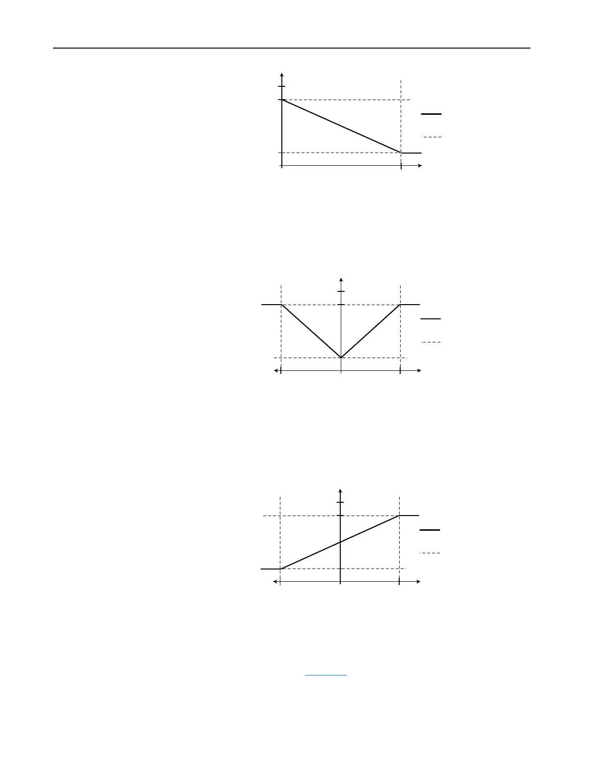
Example 4 – Signed Output Quantity, Absolute Value Disabled
• [Analog Out1 Sel] = “Output Torque Current”
• [Analog Out1 Lo] = 1 volt
• [Analog Out1 Hi] set to 9 volts
• [Anlg Out Absolut] set so that absolute value is disabled for output 1.
Filtering
Software filtering will be performed on the analog outputs for certain signal
sources, as specified in
Table 2.C. “Filter A” is one possible such filter, and
it is described later in this section. Any software filtering is in addition to
any hardware filtering and sampling delays.
10V
[Analog Out1 Lo]
[Analog Out1 Hi]
0V
0% 200%
Output Current
Analog
Output Voltage
Output Current vs.
Analog Output Voltage
Marker Lines
10V
[Analog Out1 Hi]
[Analog Out1 Lo]
0V
0% 200%200%
Output Torque Current
Analog
Output Voltage
Output Torque Current vs.
Analog Output Voltage
Marker Lines
10V
[Analog Out1 Hi]
[Analog Out1 Lo]
0V
0% 200%200%
Output Torque Current
Analog
Output Voltage
Output Torque Current vs.
Analog Output Voltage
Marker Lines

 Loading...


