Configuring Communication
34
MVP-5200i Modero® ViewPoint® Touch Panel with Intercom - Instruction Manual
NOTE: WEP will not work unless the same Default Key is set on both the panel and the Access Point. For example, if the Access
Point has been set to default key 4 (which was 01:02:03:04:05), the panel’s key 4 must be set to 01:02:03:04:05.
6. Toggle the Default Key field to choose a WEP Key value (from 1- 4) that matches what will be used on the target.
NOTE: The WEP Key identifier values must match for both devices.
7. Click Save to return to the Wireless Settings page.
8. Verify that the fields within the IP Settings section have been properly configured. Refer to Step 1: Configure the Device’s
Wireless IP Settings section on page 29 for detailed information.
9. Press the Back button to navigate to the Protected Setup page. Remember that you will need to navigate to the System
Settings page and configure the connection to a target Master.
10. Return to the Wireless Settings page to verify the Signal Level and Signal Level Value.
NOTE: The Signal Level bar provides some descriptive text regarding the strength of the connection to a Access Point. Configuration
of the network could be required if there is no signal or no IP Address is displayed.
Conf iguring Multiple Wireless Touch Panels To Communicate To a Target AP
1. For each communicating touch panel, complete all of the steps outlined within the Automatically Setting SSID section on
page 33.
2. Navigate back to the Wireless Settings page on each panel.
3. Verify that all communicating Modero panels are using the same SSID, encryption level, Default Key #, and an identical
Current Key value.
As an example, all panels should be set to Default Key #1 and be using aa:bb:cc.as the Current Key string value. This same Key
value and Current Key string should be used on the target AP.
4. Repeat steps 1 - 3 on each panel.
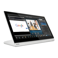
Ethernet Over USB
The MVP-5200i device is the first G4 device to support an "Ethernet over USB" driver for panel downloads and firmware updates.
This means that the device can connect to a host computer for updates through its Mini USB port instead of through a standard
Ethernet port (FIG. 28).
Because of its Ethernet over USB capabilities, the MVP-5200i also follows a different procedure for downloading firmware than with
other G4 devices.
Firmware downloads require use of the USB Programming Cable (FG10-5965) and a computer running Windows XP.
Touch Panel Setup
To prepare the MVP-5200i for Ethernet for USB communication:
1. Turn on the MVP-5200i and wait for the device to finish booting up.
2. Insert the mini-USB end of the USB Programming Cable into the mini-USB port on the device. Insert the other end into the
appropriate USB port on the computer containing the files to be downloaded.
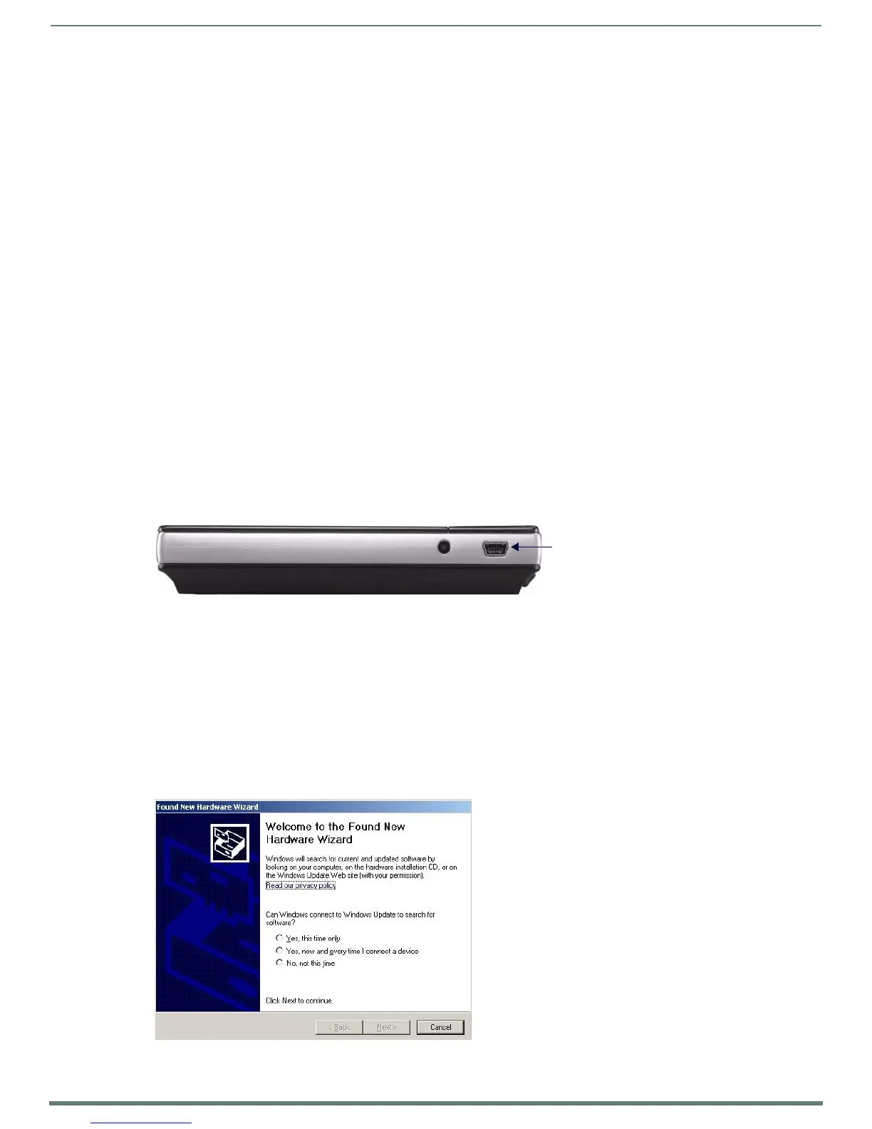
3. If the connection goes well, the Windows XP machine will detect the device as an unsupported USB device. It then presents a
dialog that prompts the user for a suitable driver (FIG. 29):
FIG. 28
USB Port on the MVP-5200i
FIG. 29 Found New Hardware Wizard dialog

 Loading...