MP-1xx SIP
MP-1xx SIP User’s Manual 32 Document #: LTRT-65404
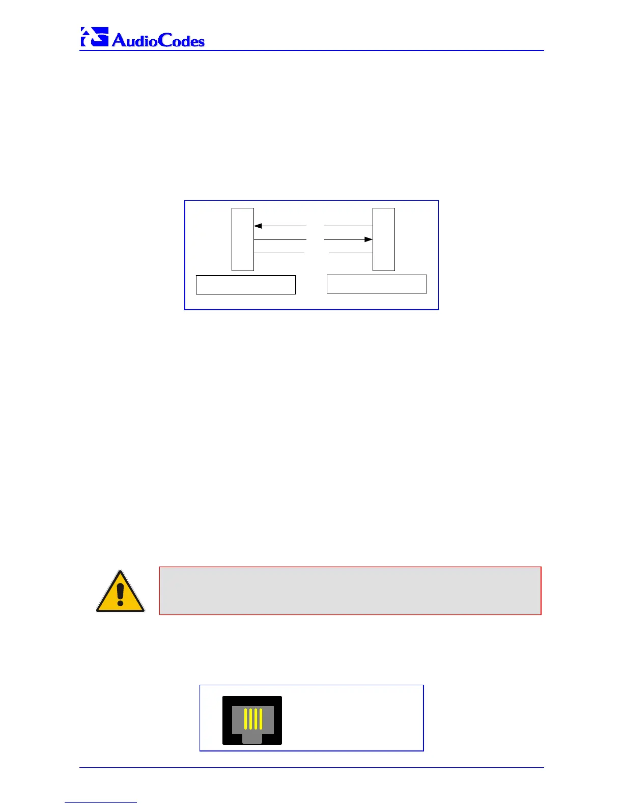
3.4.1 Connecting the MP-1xx RS-232 Port to Your PC
Using a standard RS-232 straight cable (not a cross-over cable) with DB-9 connectors, connect
the MP-1xx RS-232 port to either COM1 or COM2 RS-232 communication port on your PC. The
required connector pinout and gender are shown below in Figure
3-10.
The RS-232 port is mainly used internally by service personnel for monitoring purposes.
Advanced users can also use this feature to obtain log information (for example).
Figure 3-10: RS-232 Cable Wiring
2
3
5
2
3
5
RD
TD
GND
DB-9 female for PC DB-9 male for MP-100
3.4.1.1 Configuring the Serial Connection
To communicate with the MP-1xx, set your serial communication software to the following
communications port settings:
• Baud Rate: 115,200 bps
• Data bits: 8
• Parity: None
• Stop bits: 1
• Flow control: Hardware
3.4.2 Cabling the Lifeline Phone
The Lifeline provides a wired analog POTS phone connection to any PSTN or PBX FXS port
when there is no power, or when the network connection fails. Users can therefore use the
Lifeline phone even when the MP-1xx is not powered on or not connected to the network. With
the MP-108/FXS and MP-104/FXS the Lifeline connection is provided on port #4 (refer to Figure
3-12). With the MP-102/FXS the Lifeline connection is provided on port #2.
Note: The MP-124 and MP-10x/FXO do NOT support the Lifeline.
The Lifeline’s Splitter connects pins #1 and #4 to another source of an FXS port, and pins #2 and
#3 to the POTS phone. Refer to the Lifeline Splitter pinout in Figure
3-11.
Figure
3-11: Lifeline Splitter Pinout & RJ-11 Connector for MP-10x/FXS
1 2 3 4
1 -
2 -
3 -
4 -
Life Line Tip
Life Line Ring
Tip
Ring
DB-9 female for PC
DB-9 male for MP-1xx
 Loading...