4
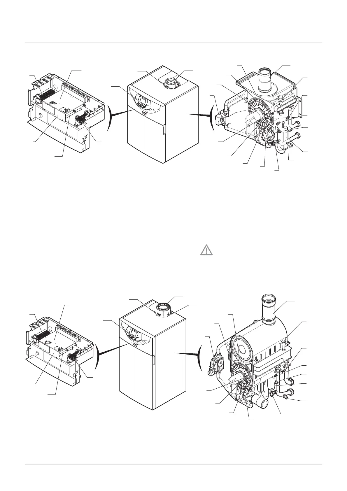
Fig.9 POWER HT+ 1.50 and POWER HT+ 1.70
MW-3000116-01
1
2
7
8
24
20
4
322
9
10
11
21
12
13
14
6
15
16
1923
18
17
5
Control panel
Flue gas measuring point
Flue gas connection
Power supply terminal block
Terminal block for the sensors and the remote con
trol
Controller PCB
Gas valve
Burner
Flue gas fitting
Automatic air vent
Return sensor
Safety thermostat
Condensate siphon
Drain valve
Hydraulic pressure sensor
Igniter
Spark plug
Ionisation probe
Flame inspection window
Flue gas sensor
Flow temperature sensor
Emplacement for two AVS 75 boards maximum. A
third AVS 75 board can be used by the boiler but
must be fixed to the wall and powered externally.
Emplacement for OCI 345 board
Danger of short circuit on the OCI 345 board if
it is fixed in another emplacement.
Safety thermostat on the combustion chamber door
Fig.10 POWER HT+ 1.90 and POWER HT+ 1.110
MW-3000117-01
1
2
3
2022
5
6
4
9
10
11
21
14
15
16
12
13
7
8
24
19
23
18
17
Control panel
Flue gas measuring point
Flue gas connection
Power supply terminal block
Terminal block for the sensors and the remote con
trol
Controller PCB
Gas valve
Burner
Flue gas fitting
Automatic air vent
Return sensor
4 Description of the product
20 7609474 - v02 - 04092014
 Loading...


