P
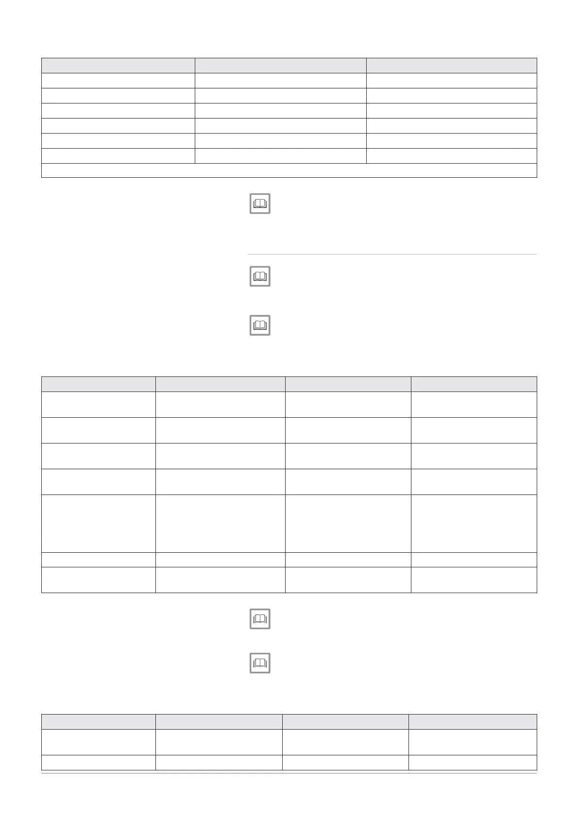
Parameter number Parameter Setting
6020 F
Function extension module 1 Multifunctional
6046 F
Function input H2 module 1 Consumer request VK1 10V
6049 V
Voltage value 1 H2 module 1 0
6050 F
Funct value 1 H2 module 1 0
6051 V
Voltage value 2 H2 module 1 10
6052 F
Funct value 2 H2 module 1
800
(1)
(1) This parameter setting is an example. The value 800 means that, at 10V, the set point will be 80°C.
List of installer parameters, page 74.
7.5.4 Configuring a lead boiler and the secondary boilers in a cas
cade
See
Connecting boilers in cascade with an OCI 345 interface, page 54.
1. Access the installer parameters of the lead boiler.
Modifying the installer parameters, page 68.
2. Set the following parameters on the lead boiler:
Tab.33 Configuration cascade lead boiler
Parameter number Parameter Setting Description
5977 F
Deactivation of the thermostat
on terminal block M
6030 R
Relay output QX21 module 1 heating pump CH1 Q2
Check on the pump on circuit
1
6040 S
Sensor input BX21 module 1 Common flow sensor B10
Check on the cascade flow
temperature
6041 S
Sensor input BX22 module 1 Cascade return sensor B70
Check on the cascade return
temperature
6200 S
Saving any modifications
made.
The setting will revert auto
matically to N
immediately af
ter the adjustment.
6630 C
Identification lead boiler
6640 C
Cascade lead boiler clock set
ting
List of installer parameters, page 74.
3. Access the installer parameters of the secondary boiler(s).
Modifying the installer parameters, page 68.
4. Set the following parameters on the secondary boiler(s).
Tab.34 Configuration cascade secondary boilers
Parameter number Parameter Setting Description
5710 T
Deactivation of the thermostat
on terminal block M
6600 D
Device address 2...3...4...
Cascade activation
7 Commissioning
66 7609474 - v02 - 04092014
 Loading...


