7
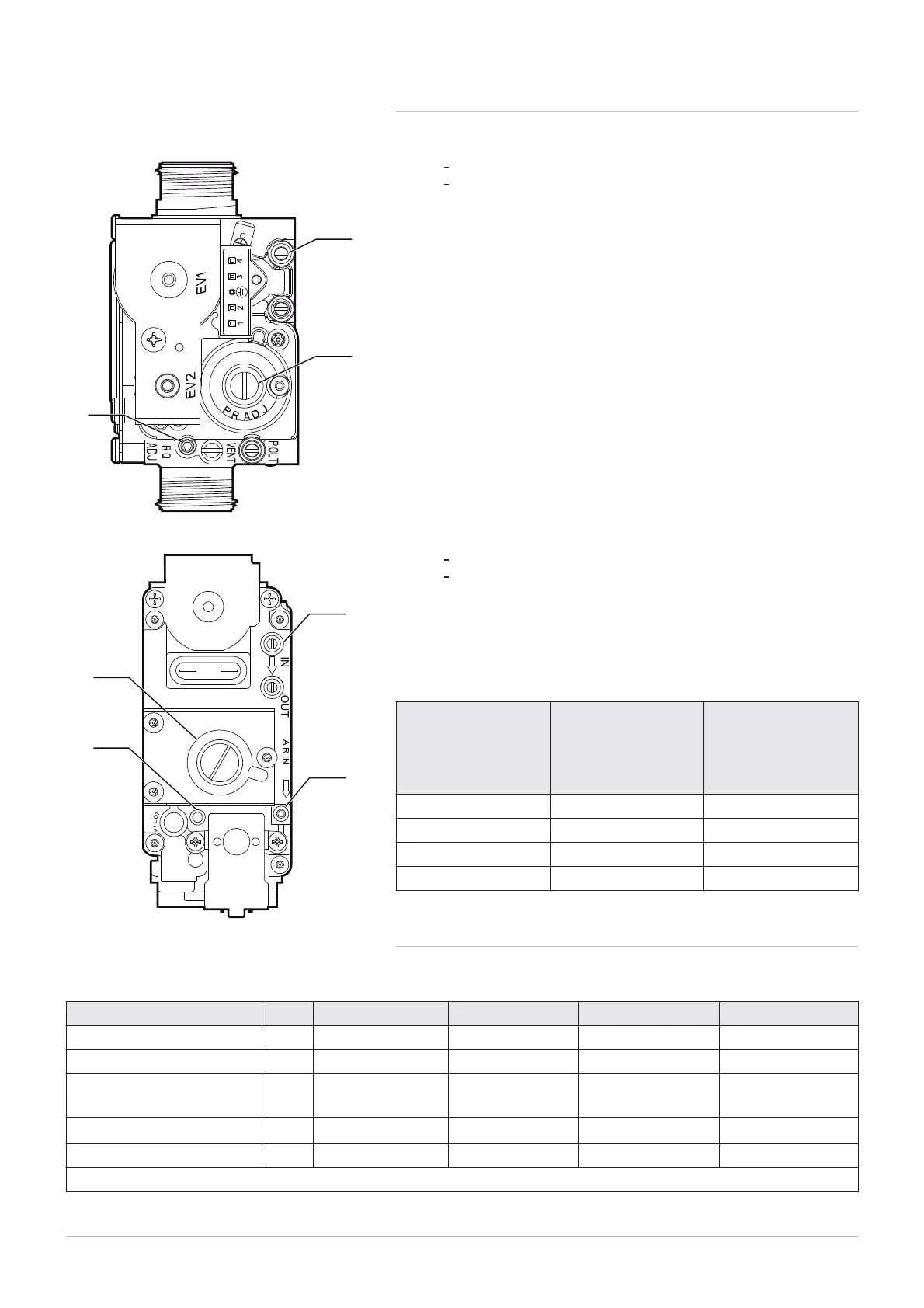
Gas flow rate setting screw
OFFSET setting screw:
Remove the plug
Use a 4 mm hexagonal spanner
Gas supply pressure outlet
Gas flow rate setting screw
OFFSET setting screw:
Remove the plug
Use a flat-blade screwdriver
Sealed chamber pressure signal
Gas supply pressure outlet
Tab.23 Settings values for a new gas valve on POWER HT +
The settings screw is screwed down as far as it will go and is then is un
screwed according to the number of turns given in the following table.
Boiler model Nominal heating flow
rate:
Number of turns for the
gas flow rate settings
screw
Minimum heating flow
rate:
Number of turns for the
OFFSET settings
screw
POWER HT+ 1.50 12 5 + 3/4
POWER HT+ 1.70 13 5 + 3/4
POWER HT+ 1.90 2 + 2/3 5 + 3/4
POWER HT+ 1.110 2 + 1/3 5 + 3/4
7.4.5 CO
2
checking and setting values
Tab.24 Checking and setting values for gas type G20
Unit POWER HT+ 1.50 POWER HT+ 1.70 POWER HT+ 1.90 POWER HT+ 1.110
Diameter of the Venturi mm 24 30 34 38
Diameter of the nozzles mm 3.70 (no. 2) 5.30 (no. 2) 5.60 (no. 2) 6.40 (no. 2)
Minimum CO
2
(1)
% 8.5 8.5 8.5 9.0
Maximum CO
2
(1)
% 9.0 9.0 9.0 9.2
Maximum CO ppm < 250 < 250 < 250 < 250
(1) The CO
2
value is valid with the front panel mounted. If the front panel is removed (open chamber), the value readout is lower by 0.2%.
Fig.66 POWER HT+ 1.50 – POWER HT+
1.70
MW-3000045-01
1
2
3
Fig.67 POWER HT+ 1.90 – POWER HT+
1.110
MW-3000047-01
3
1
2
4
7 Commissioning
62 7609474 - v02 - 04092014
 Loading...


