6. Remove the detachable panel if necessary.
S
The disassembly instructions can be found on the detachable pan
el.
6.3 Water connections
6.3.1 Connection of the heating circuit
Abide by the mountings shown in the hydraulic diagrams.
Connecting diagrams, page 33.
The heating pipe must be mounted in accordance with the provi
sions applicable.
If installing isolation valves, position the fill/drain valve and the
expansion vessel between the isolation valves and the boiler.
Always install a safety valve calibrated to 4 bar on the heating
circuit. The safety valve can be connected to a venting pot. The
safety valve must not be used to drain the heating circuit.
In the case of an assembly with a low-loss header, use the as
sembly instructions for the low-loss header.
If using a cascade kit, use the assembly instructions for the cas
cade kit.
The pipes are not provided.
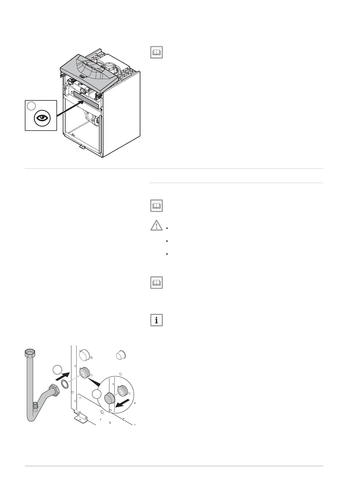
1. Remove the anti-dust plug located on the boiler's "heating flow" out
let.
2. Connect the "heating circuit flow" pipe to the boiler's "heating flow"
outlet.
Fig.40 Location of the disassembly instruc
tions
MW-3000026-01
6
Fig.41 Connecting the "heating circuit flow"
pipe
MW-3000028
1
2
6 Installation
7609474 - v02 - 04092014 39
 Loading...


