5
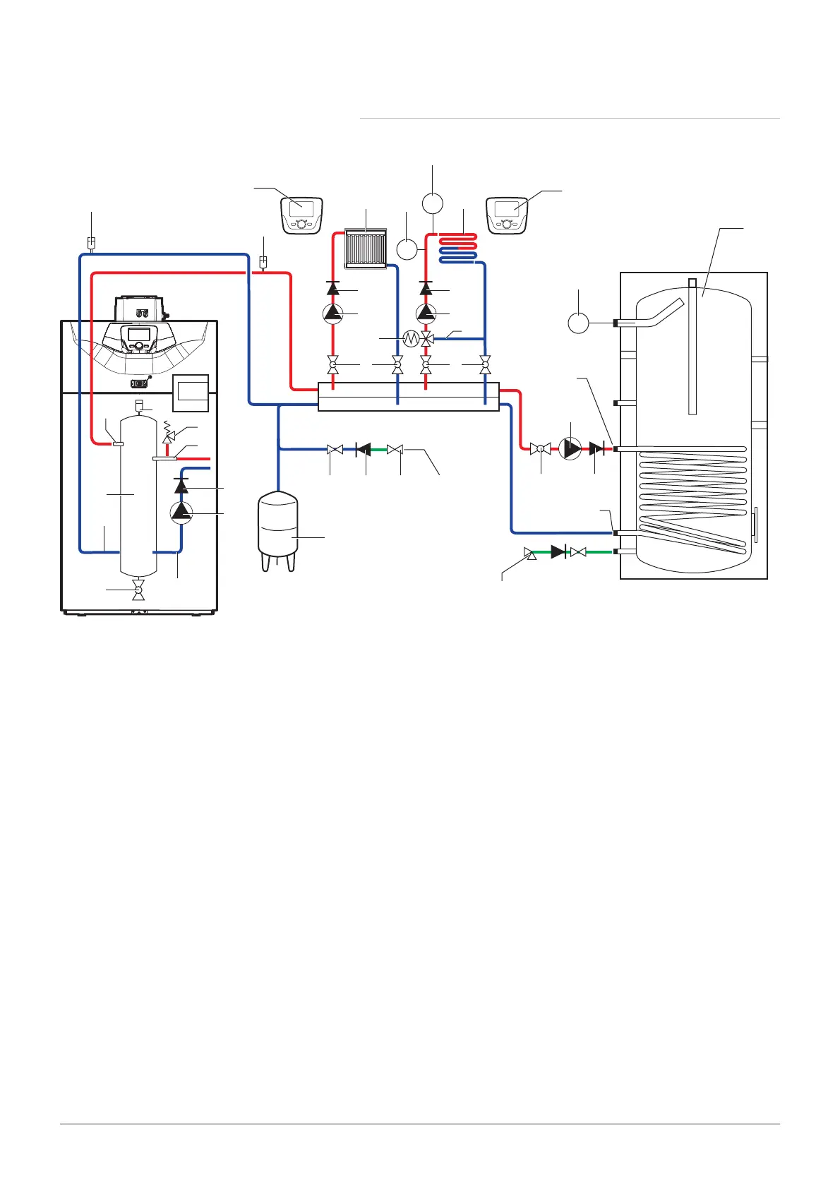
5.7.2 Connection diagram: 1 boiler + 1 direct circuit + 1 underfloor
heating circuit + 1 domestic hot water tank
Fig.32 1 boiler + 1 direct circuit + 1 underfloor heating circuit + 1 domestic hot water tank
MW-3000019-01
30
T
7
7
31
24
25
33
9 9
1a
35
2a
119
30e
7
16
27 18
38
38
9
T
S
44
61
932
2727
9
117
6564
9
26
27
2c
27
34
1
3
Boiler flow
Heating flow
Heating pump
Heating return
3-way valve bypass
4 bar safety valve (0.4 MPa)
Automatic air vent
Isolation valve
Closed expansion vessel
Filling the heating circuit
Domestic hot water tank exchanger primary inlet
Primary exchanger outlet domestic hot water tank
DHW load pump
Non-return valve
Calibrated and sealed safety unit
Drain valve
Independent domestic hot water tank
Domestic hot water temperature sensor
Modulating boiler pump
Disconnecting cylinder (optional)
Remote control with or without room temperature
sensor
Safety device to safeguard against overheating of
the underfloor heating system, in accordance with
prevailing regulations
Thermometer
Direct heating circuit (example: radiators)
Heating circuit with mixing valve, may be low tem
perature heating circuit (underfloor heating or radia
tors)
Underfloor heating circuit heating pump
3-way mixing valve
Boiler return
5 Before installation
34 7609474 - v02 - 04092014
 Loading...


