1
Reversing valve 1
Flow temperature sensor
Configuring an installation with 1 boiler + 1 low-loss header + 1 di
rect circuit + 1 underfloor heating circuit + domestic hot water
tank, page 64.
Connection diagram: 1 boiler + 1 direct circuit + 1 underfloor heat
ing circuit + 1 domestic hot water tank, page 34.
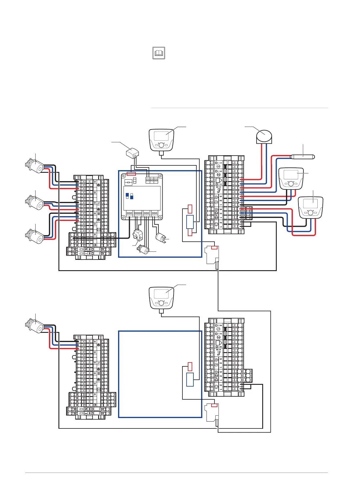
6.6.9 Electrical connection: Boilers in cascade + 1 direct circuit +
1 underfloor heating circuit + 1 domestic hot water tank
Fig.61 Boilers in cascade + 1 direct circuit + 1 underfloor heating circuit + 1 domestic hot water tank
1
2
3
4
Aux 1-2 230 V
TA TS
LN LN L LNNLNLN
1
2
3
4
Aux 1-2 230 V
TA TS
LN LN L LNNLNLN
MW-3000040-01
38
200
201
38
158
117
2
44
34
34
26
11
21
38
33
38
AVS75
OCI345
OCI345
123
123
Heating pump
Heating pump
Outside temperature sensor
DHW load pump
Domestic hot water temperature sensor
Primary pump
Remote control with or without room temperature
sensor
6 Installation
7609474 - v02 - 04092014 53
 Loading...


