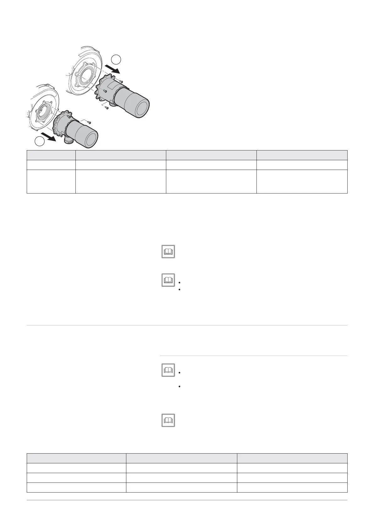
3. Remove the Venturi unit.
4. Replace the Venturi unit with the Venturi unit provided in the conver
sion kit.
5. Remount the connection pipe to the gas valve.
Tab.28 Torque
R
Reference Model Fastening Venturi end Fastening gas valve end
A
POWER HT+ 1.50 Clip G1” nut, Torque: 40 N·m
POWER HT+ 1.70
POWER HT+ 1.90
POWER HT+ 1.110
Nut, Torque: 40 N·m Nut, Torque: 40 N·m
6. Open the mains gas valve.
7. Check the tightness of the assembly and ensure that there are no
leaks.
8. Set the gas valve according to the parameters given in the conver
sion kit manual.
9. Set the fan speed according to the new gas type.
CO2 checking and setting values, page 62
10. Set the air/gas ratio.
Setting the air/gas ratio (maximum thermal flow rate), page 59.
Setting the air/gas ratio (reduced thermal flow rate), page 61.
11. Replace the gas setting label with the one delivered with the boiler
and tick the corresponding gas setting.
7.5 Checks and adjustments after commissioning
7.5.1 Configuring an installation with 1 boiler + 1 low-loss header
+ 1 direct circuit + 1 underfloor heating circuit + domestic hot water
tank
See
Connection diagram: 1 boiler + 1 direct circuit + 1 underfloor
heating circuit + 1 domestic hot water tank, page 34.
Electrical connection: 1 boiler + 1 direct circuit + 1 underfloor
heating circuit + domestic hot water tank, page 52.
1. Go to the installer parameters.
Modifying the installer parameters, page 68.
2. Set following parameters on the boiler:
Tab.29 Boiler settings
Parameter number Parameter Setting
5715 T
6020 F
Function extension module 1 Temps / mode CH2
6024 F
Funct input EX21 module 1 Limit thermostat CH
Fig.69 Removing the Venturi unit
MW-3000049
A
B
3
3
7 Commissioning
64 7609474 - v02 - 04092014
 Loading...


