C
All connections are made to the terminal blocks provided for that
purpose in the boiler connection box. The available output per out
let is 180 W (1A, with cos ϕ = 0.8) and the inrush current must be
lower than 5A. If the load exceeds either of these values, the con
trol must be relayed using a contactor that must not be installed in
the control panel under any circumstances. The sum of the cur
rents from all outlets must not exceed 4 A.
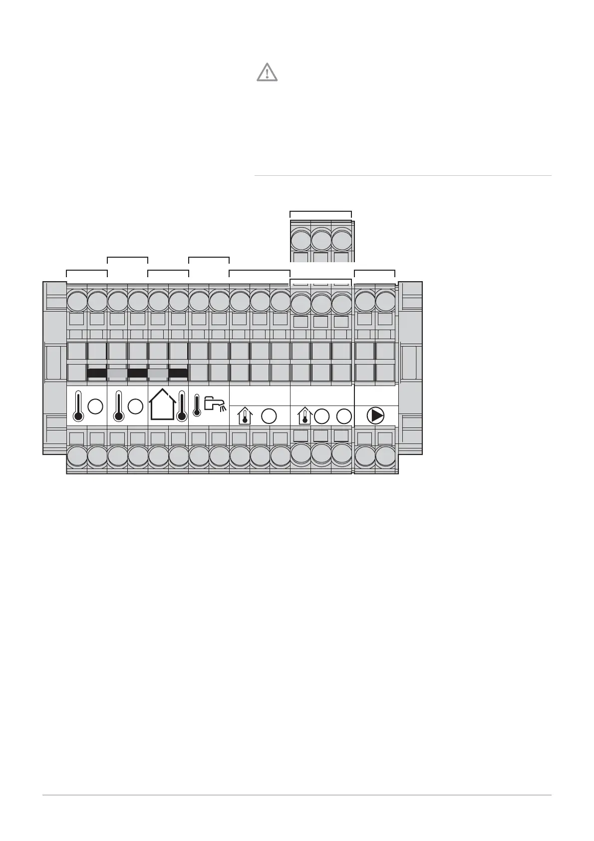
6.6.6 Description of the sensor terminal block
Fig.58 Sensor terminal block
MW-1000016-02
1
1
2
12312123
2
/
3
1
2
3
4
5
6
8
7
Auxiliary sensor 1
Auxiliary sensor 2
Outside temperature sensor
Domestic hot water sensor
Room temperature sensor 1
Room temperature sensor 2
Room temperature sensor 3
Boiler pump modulation (PWM)
6 Installation
7609474 - v02 - 04092014 51
 Loading...


